Supercharge Your Innovation With Domain-Expert AI Agents!

Sub picture element displacement detecting method applied to optical track navigation element

A displacement, sub-pixel technology, applied in the input/output process of data processing, instruments, electrical digital data processing and other directions, can solve the problem of inability to judge the movement trajectory

Inactive Publication Date: 2009-04-29
SUNPLUS TECH CO LTD
View PDF3 Cites 0 Cited by
  • Summary
  • Abstract
  • Description
  • Claims
  • Application Information

AI Technical Summary

Problems solved by technology

Secondly, this method needs to refer to the entire image range, that is, this method needs to use the search window to calculate the correlation, and when the amount of movement is large so that the reference image range (the second image) is larger than the search window, this method cannot judge moving track

Method used


Image

  • Sub picture element displacement detecting method applied to optical track navigation element
  • Sub picture element displacement detecting method applied to optical track navigation element
  • Sub picture element displacement detecting method applied to optical track navigation element

Examples


Embodiment Construction

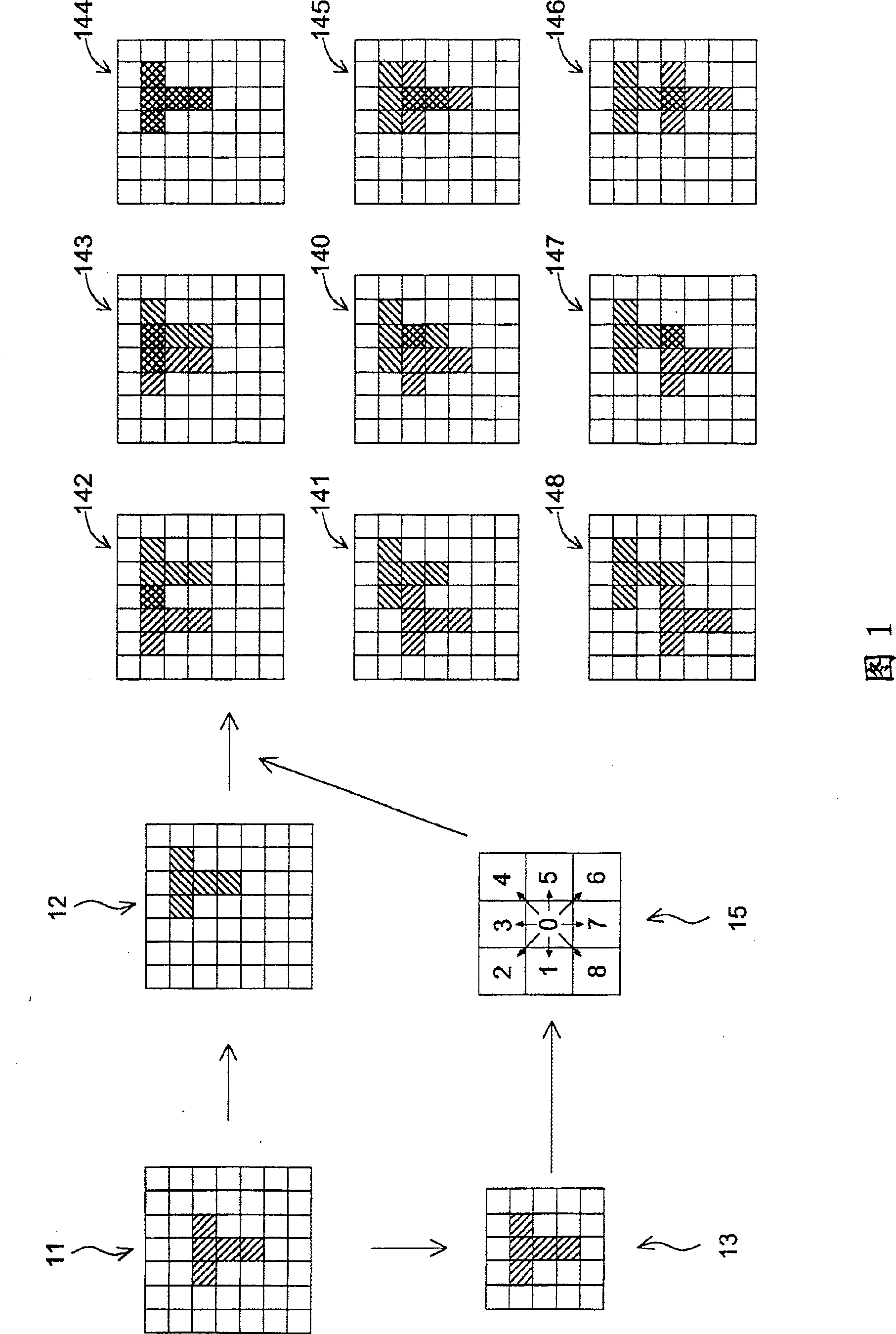
[0051] The method for detecting sub-pixel displacement applied to an optical track navigation device according to the present invention will be described in detail below with reference to a specific embodiment and accompanying drawings.

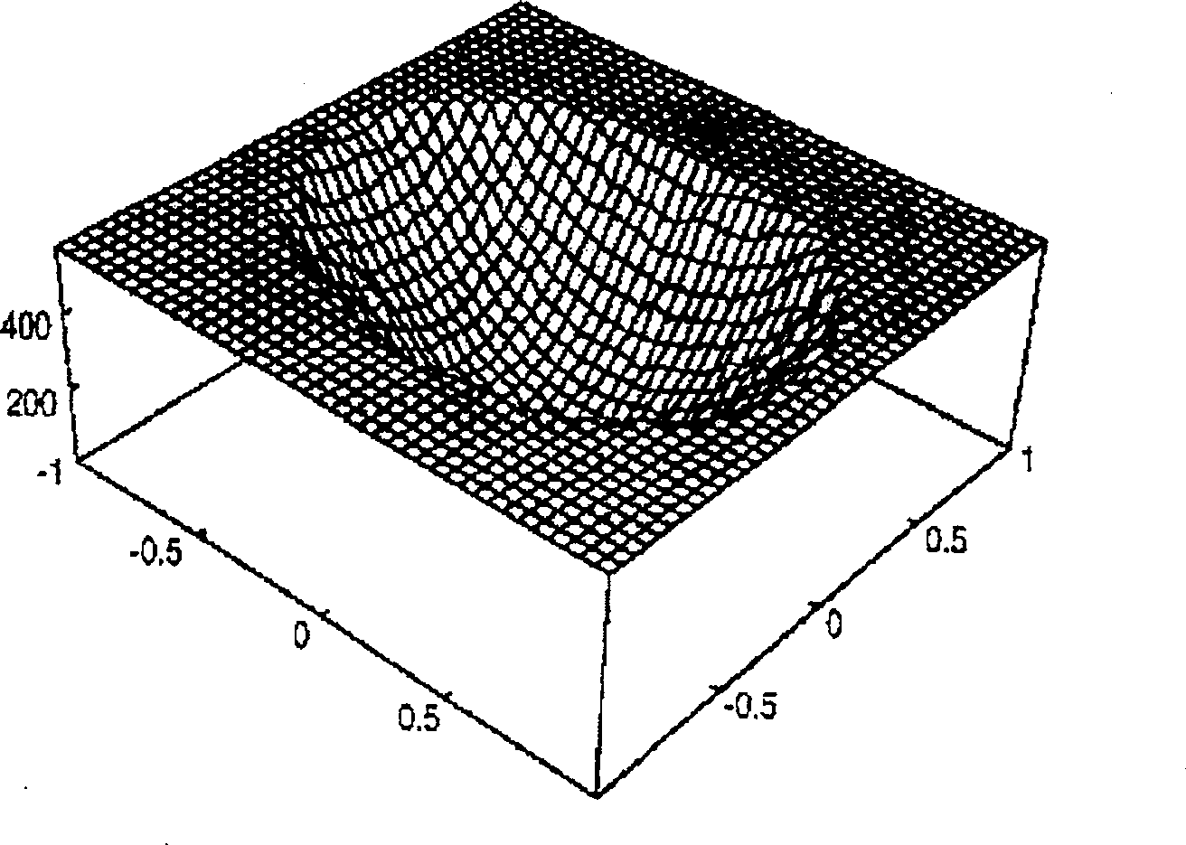
[0052] Figure 4 Shown is the relationship between position and brightness, where the x-axis is the horizontal axis and the brightness is the vertical axis. The dotted curve is the brightness curve Ir of the previous image, and the solid-line curve is the brightness curve Is of the current image. If it is assumed that the brightness of the two images is the same, but the positions are different, the relationship between the brightness curve Ir and Is is:

[0053] Is (x, y) = Ir (x + Δx, y + Δy) ... (1)

[0054] The formula (1) is expanded by Taylor expansion method, and only the first order partial differential is listed, then the formula (1) can be expanded as:

[0055]

[0056] for In terms of, it can be regarded as the slope (bright...


PUM


Abstract

The subpixel displacement detecting method for optical locus navigation element calculates the displacement with the simultaneous equations established in the first-order partial differential function of Taylor's expansion. The detection process includes the following steps: taking the first image and the second image; selecting several image points as calculation reference points; calculating partial differential amounts of the first-order partial differential function of Taylor's expansion of the reference points to generate several binary first order equations; and calculating the pixel displacements. The reference points for calculation are reliable points with monotonic brightness change greater than some critical value, and may be classified for calculating displacement via summing various kinds of coefficients to suppress noise.

Description

technical field [0001] The invention relates to a sub-pixel displacement detection method applied to an optical track navigation element, in particular to a sub-pixel displacement detection method using Taylor expansion to obtain the displacement. Background technique [0002] The optical mouse uses the sub-pixel displacement detection method of the optical track navigation element to identify the displacement of the mouse. However, the conventional sub-pixel displacement detection method using the optical track navigation element uses a partial image of the first image as a search window (search window), and uses the search window to correlate with the second image at different positions ( correlation) calculation. Afterwards, a quadratic surface is correspondingly calculated according to the magnitude of the calculated correlation, and then an absolute minimum value is found from the quadratic surface as a displacement amount. US Patent No. 5,729,008 "Method and device f...

Claims


Application Information

Patent Timeline
IPC IPC(8): G06F3/033G06F3/0354
Inventor 辜维欣林焜尉林俊宏
Owner SUNPLUS TECH CO LTD
Features
  • R&D
  • Intellectual Property
  • Life Sciences
  • Materials
  • Tech Scout
  • Unparalleled Data Quality
  • Higher Quality Content
  • 60% Fewer Hallucinations
Learn More