Staple device

A technology for stapling books and staples, which is applied in the direction of nailing U-shaped nail tools, nailing tools, manufacturing tools, etc. It can solve the problems of difficult long-distance transportation, heavy load, and falling of nail boxes, and achieve good productivity. , Improve operability, and realize the effect of miniaturization

Inactive Publication Date: 2009-05-13
MAX CO LTD
View PDF11 Cites 0 Cited by
  • Summary
  • Abstract
  • Description
  • Claims
  • Application Information

AI Technical Summary

Problems solved by technology

However, it has the following disadvantages: in order to convey the reel-shaped staples with the conveying claws, it is necessary to form the front end side of the reel-shaped staples into a flat plate; In addition to changing the movement of the motor to linear motion, it is more difficult to carry out long-distance transportation compared with the conveyor roller
However, in this case, since the operation lever is used to release the lock, the hands are temporarily removed from the operation lever, and then the hand is turned to the nail box, and the nail box is pulled out, so it is very troublesome. Different and cannot be handed over smoothly, causing the nail box to fall
Therefore, it is necessary to provide a mechanism for preventing falling of the nail box, and there is a problem that the load when pulling out the nail box using this mechanism increases.

Method used


Image

  • Staple device
  • Staple device
  • Staple device

Examples


Embodiment 1

[0086]

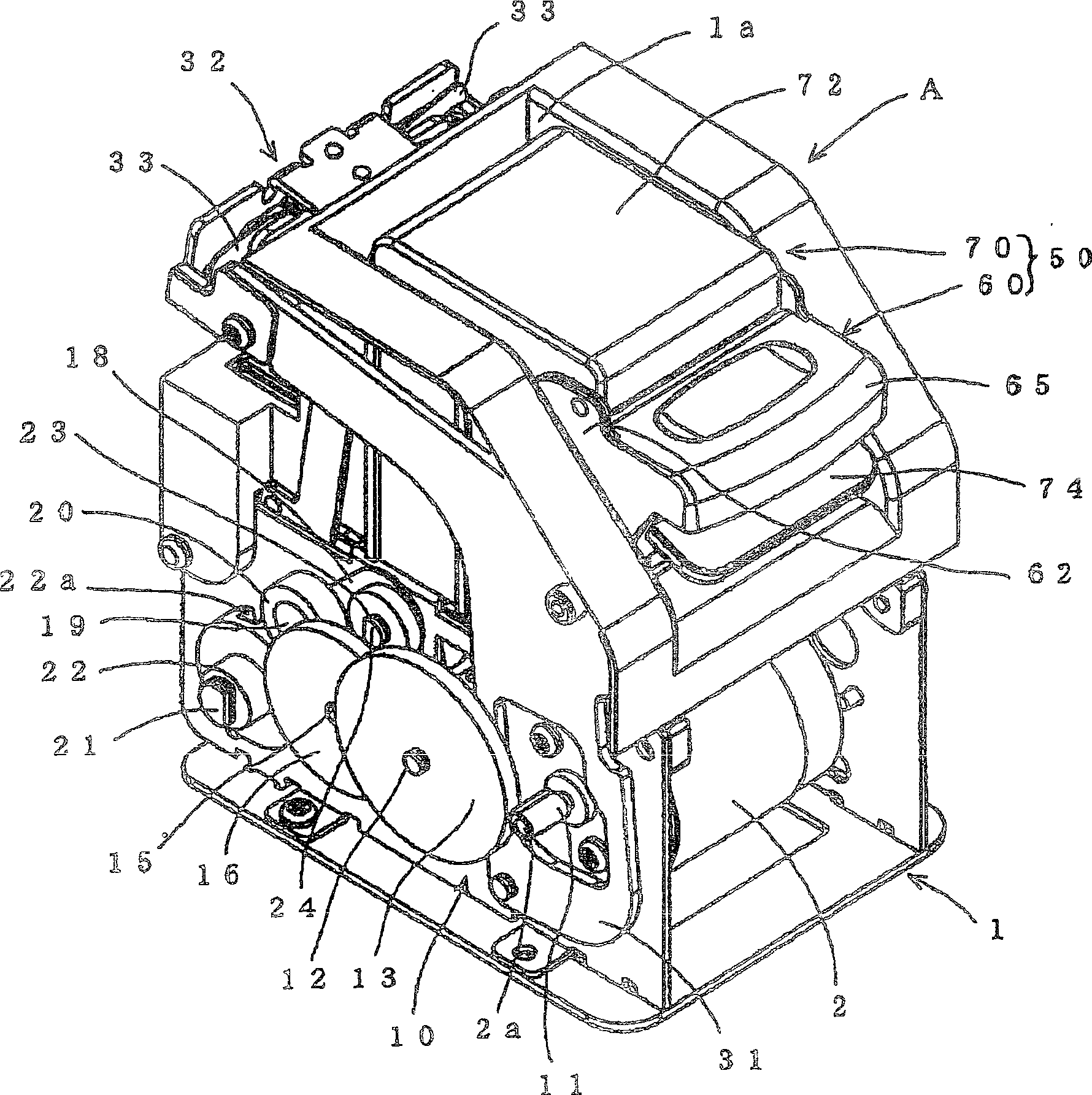
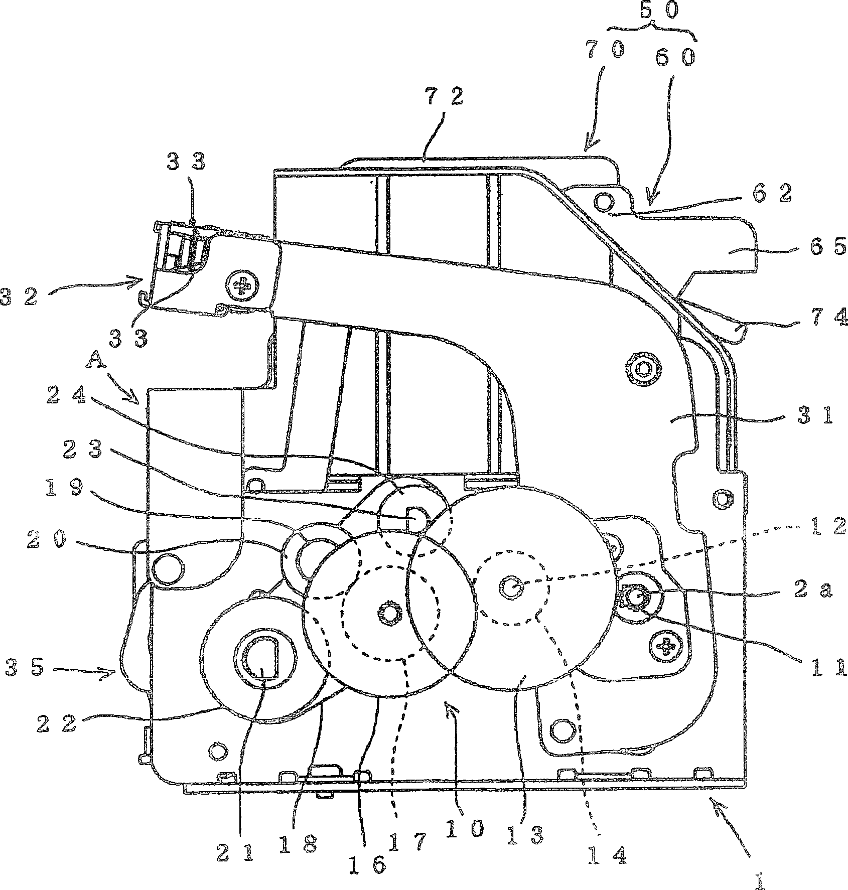
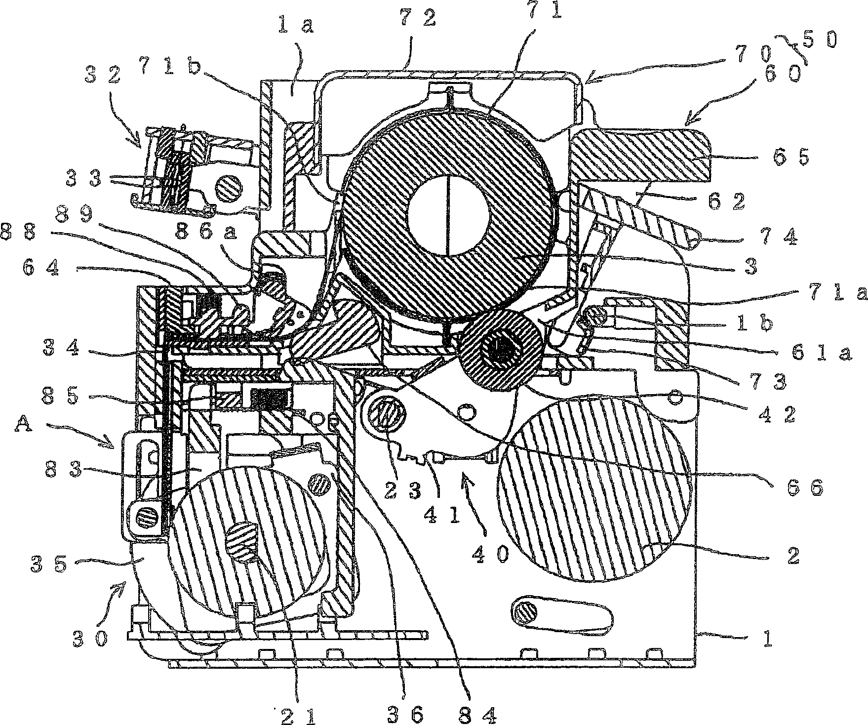
[0087] figure 1 It is a perspective view of the appearance of the stapling device according to the first embodiment of the present invention, figure 2 is a side view of the stapler, image 3 It is a longitudinal sectional view of the stapler.

[0088] exist Figure 1 ~ Figure 3 Among them, the stapler A has a main frame 1 mounted on an image forming apparatus (not shown) intended to include a post-processing apparatus such as a sorter or a finisher.

[0089] A forward and reverse drive motor 2 is fixed on the main frame 1 . In addition, the main frame 1 is equipped with: a power transmission gear part 10 for transmitting the rotational drive of the forward and reverse drive motor 2; The staple supply unit 40 that performs the staple supply operation when the forward and reverse drive motor 2 is reversed, and the staple cartridge 50 that can be attached to and detached from the main frame 1 .

[0090]

[0091] 4 shows the structure of the power transmission ...

Embodiment 2

[0136] Figure 17 It is a schematic diagram of an electric stapler (staple device) according to a second embodiment of the present invention. The electric stapler is composed of an electric stapler main body 101 and a staple cartridge 102 .

[0137] The electric stapler main body 101 has a drive link 104 that oscillates with an output shaft 103 of the motor, a forming plate 105 driven by a force transmitted from the output shaft 3 through an intermediate gear 103a, a drive plate 106, and the like. A clamp 107 is provided at the front end of the drive link 104 .

[0138] staple box 102, such as Figure 18 As shown in FIG. 1 , it includes: a storage unit 108 for storing a plurality of straight staples inside; and a driving unit 109 for driving out staples discharged from the lower end of the storage unit 108 . In addition, in the storage portion 108, a plate-shaped staple (not shown) that connects a plurality of straight staples in a plate shape is stored in a stacked state. ...


PUM


Abstract

The invention provide stapler device .A sending roller (42) is caused to be in contact with the outer periphery of a roll staple (3) constituted of a large number of straight needles connected in a belt-like shape and made in a roll-like shape. A sending roller (42) is rotated by a drive motor, and the roll staple (3) is rotated in the unwinding direction. This causes the head end of the roll staple (3) is guided and supplied to a staple supply passage (100).

Description

technical field [0001] The present invention relates to a stapling device installed in an image forming apparatus such as a copier to bind sheets of paper to be bound with a staple. Background technique [0002] Conventionally, there is known a stapler built into an image forming apparatus such as a copier that binds a plurality of sheets of paper to be bound with a staple. [0003] In addition, among such stapling devices, there is also known a stapling device in which a plurality of straight staples are connected in a belt shape and rolled into a coil shape, and housed in a staple case (for example, JP-A-2000-167782) . The coiled staples in the staple cartridge are ejected from the staple cartridge, guided to the staple supply path, and formed into a C-shape at the front end of the staple supply path, and driven out from the driving part. [0004] However, in the aforementioned stapling device, a reciprocating feed claw is used as the mechanism for feeding the staples. ...

Claims


Application Information

Patent Timeline
Patent Type & Authority Patents(China)
IPC IPC(8): B25C5/15B27F7/38B25C5/16
Inventor 长谷川隆生真锅克则
Owner MAX CO LTD
Why Eureka
Try Eureka