
Water flow controller for water spraying tool

A technology of water flow control and tools, which is applied in the direction of spraying devices, spraying devices, etc., can solve the problems of high strength, large flow rate, and high sealing requirements of water flow control devices, so as to achieve good sealing effect, increase water flow intensity, and improve water flow control effect and the effect of the sealing effect

Inactive Publication Date: 2009-06-03
TIANJIN JINMAO GROUP
View PDF5 Cites 0 Cited by
  • Summary
  • Abstract
  • Description
  • Claims
  • Application Information

AI Technical Summary

Problems solved by technology

[0004] The water flow control structure in the known technology cannot meet the requirements of thicker water rods. The thicker and longer hand-held tool rods have a larger flow of water, which requires higher sealing requirements for the water flow control device. higher strength
The market urgently needs a water flow control device that can better meet the flow and sealing requirements of thicker water rods

Method used


Image

  • Water flow controller for water spraying tool
  • Water flow controller for water spraying tool

Examples


Embodiment Construction

[0026] The specific embodiments, structures, features, and effects of the present invention will be described in detail below with reference to the accompanying drawings and preferred embodiments.

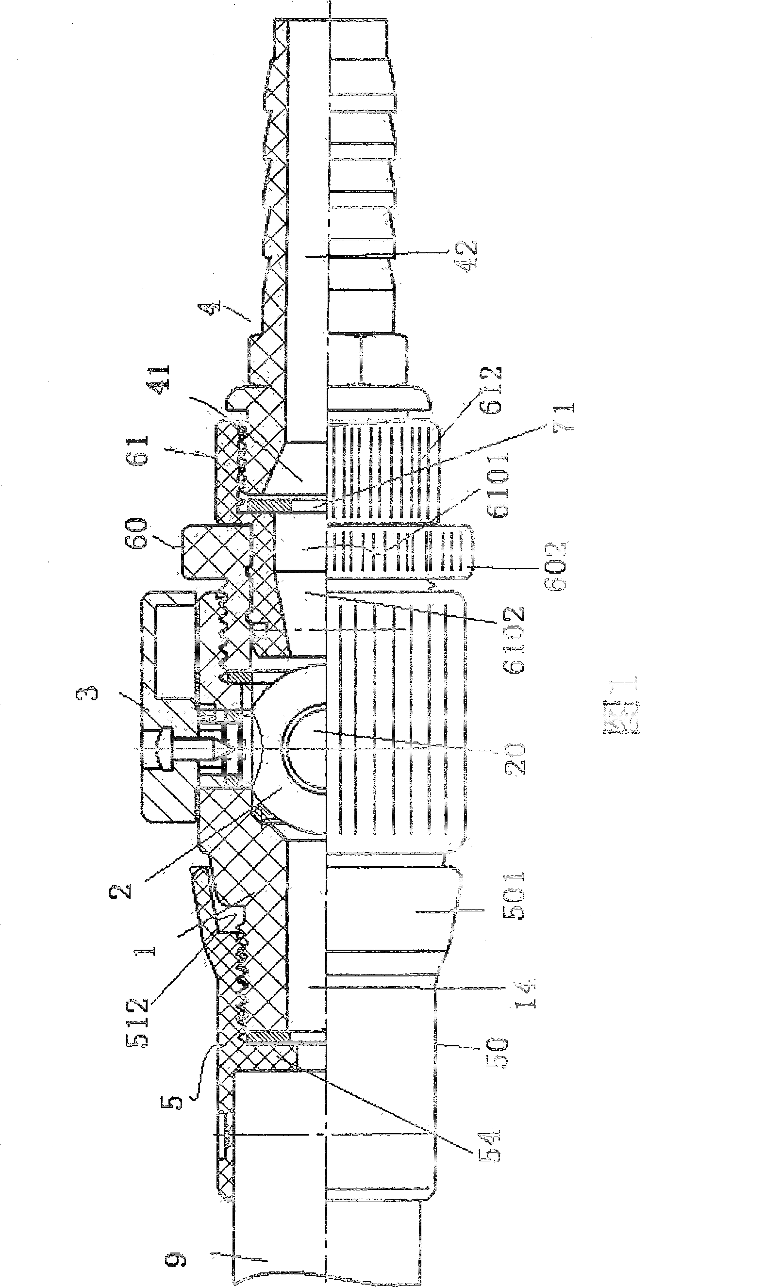
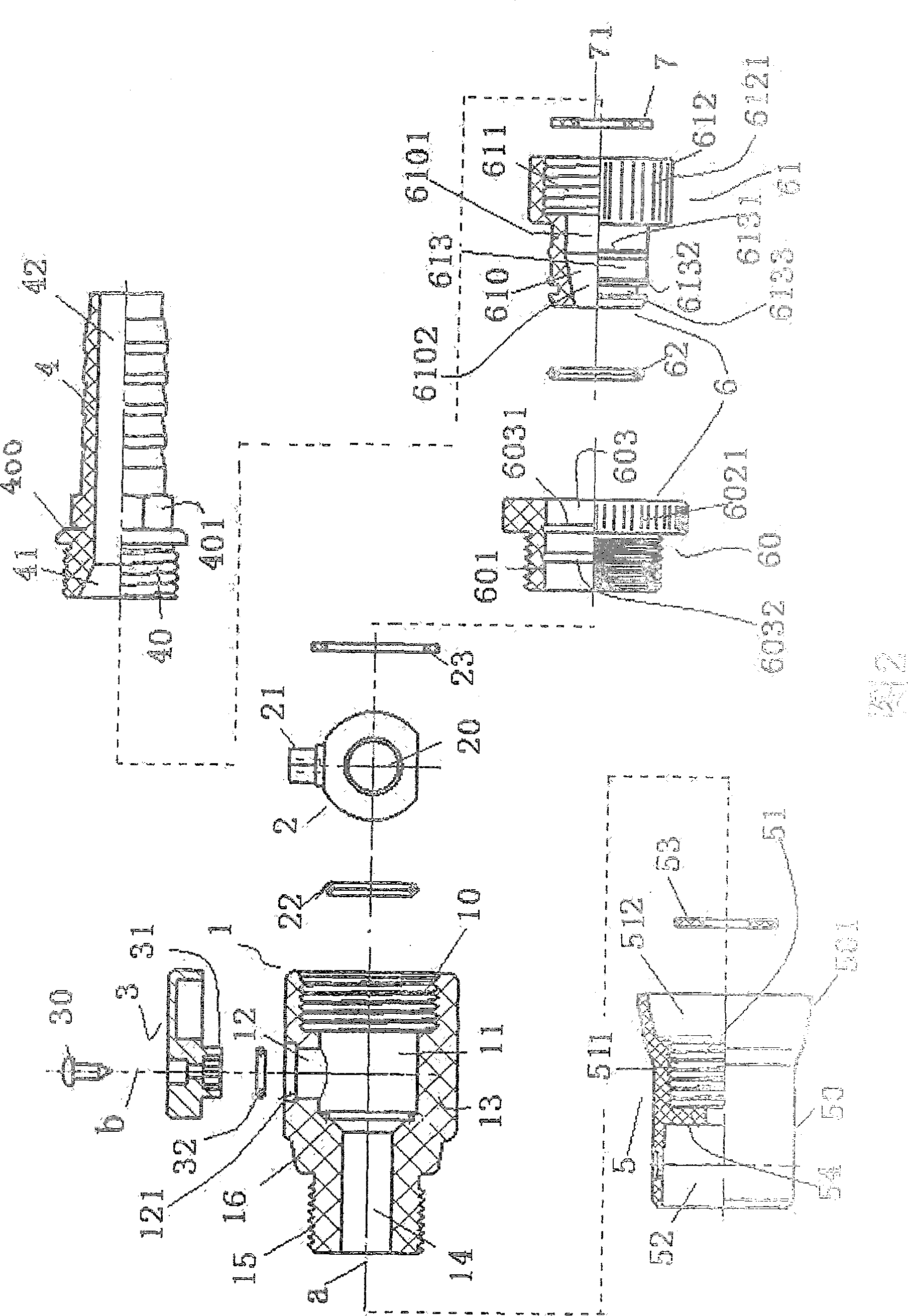
[0027] As shown in Figure 1-2, a water flow control device for a water spray tool includes a valve body 1 that can accommodate a spherical valve core 2. The spherical valve core 2 is turned by a rotary handle 3 to control the switching of water flow The main body 13 of the valve body 1 is cylindrical, one end of the main body extends outwards into a valve body water outlet coupling part 15 that is matched and combined with the rod body connector 5, and the other end of the main body has a valve body water inlet 10;

[0028] The main body 13 of the valve body is provided with a spherical valve core accommodating cavity 11 which extends upward to form a neck cavity 12 from which the handle 21 of the spherical valve core extends. The connecting end 31 of 3 is matched with the internal sto...


PUM


Abstract

The present invention is one water flow controller for water spraying tool, especially one water spraying pipe. The water flow controller includes one ball valve to control the water flow passage, one pipe connector connected to one end of the ball valve, and one water tap connector connected to the other end of the ball valve. The water tap connector has one first water accumulating cavity to form water pressure and one second water accumulating cavity in the joint to the water tap. The present invention has raised water flow controlling effect, good sealing effect, low cost and other advantages.

Description

Technical field [0001] The invention belongs to the field of water spray tools, and particularly relates to a water flow control device of a water spray rod. Background technique [0002] The conventional technology is the published Chinese patent 200320129525.2, a water spray rod that can be mixed with cleaning liquid. In order to provide a watering device component that simplifies the cleaning operation and improves the efficiency of the cleaning operation, the present invention is proposed, which includes a shunt seat, a water control valve stem, a turning knob and a cleaning liquid container; the shunt seat is provided with intersecting axial directions The top and bottom ends of the perforation and the radial piercing groove are respectively provided with first and second diversion holes and pipe group joints whose bottom ends communicate with the radial piercing groove; the water control valve stem is pivoted in the radial piercing groove, The shaft recessed arc is larger t...

Claims


Application Information

Patent Timeline
Patent Type & Authority Patents(China)
IPC IPC(8): B05B12/00B05B1/30
Inventor 李杰刘金龙杨海江李江涛
Owner TIANJIN JINMAO GROUP
Learn More