

A children unopenable switch
A switch and air technology, applied in the direction of electric switches, electrical components, circuits, etc., can solve problems such as children's easy meeting, affecting vision and learning, improper operation, etc.
- Summary
- Abstract
- Description
- Claims
- Application Information
AI Technical Summary
Problems solved by technology
Method used
Image

Examples
Embodiment 1
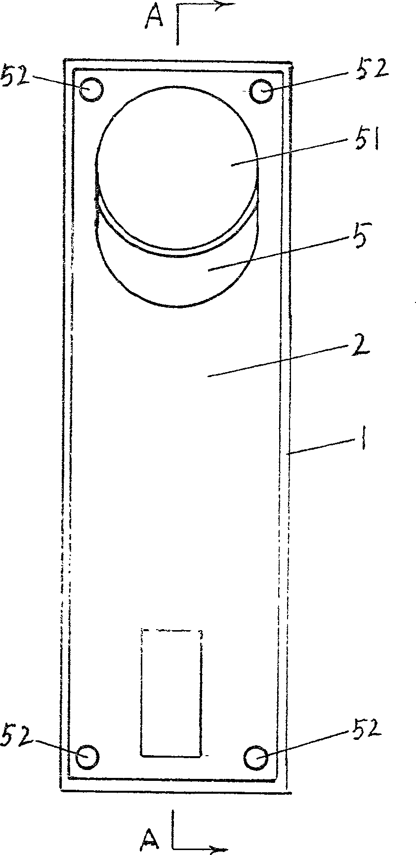
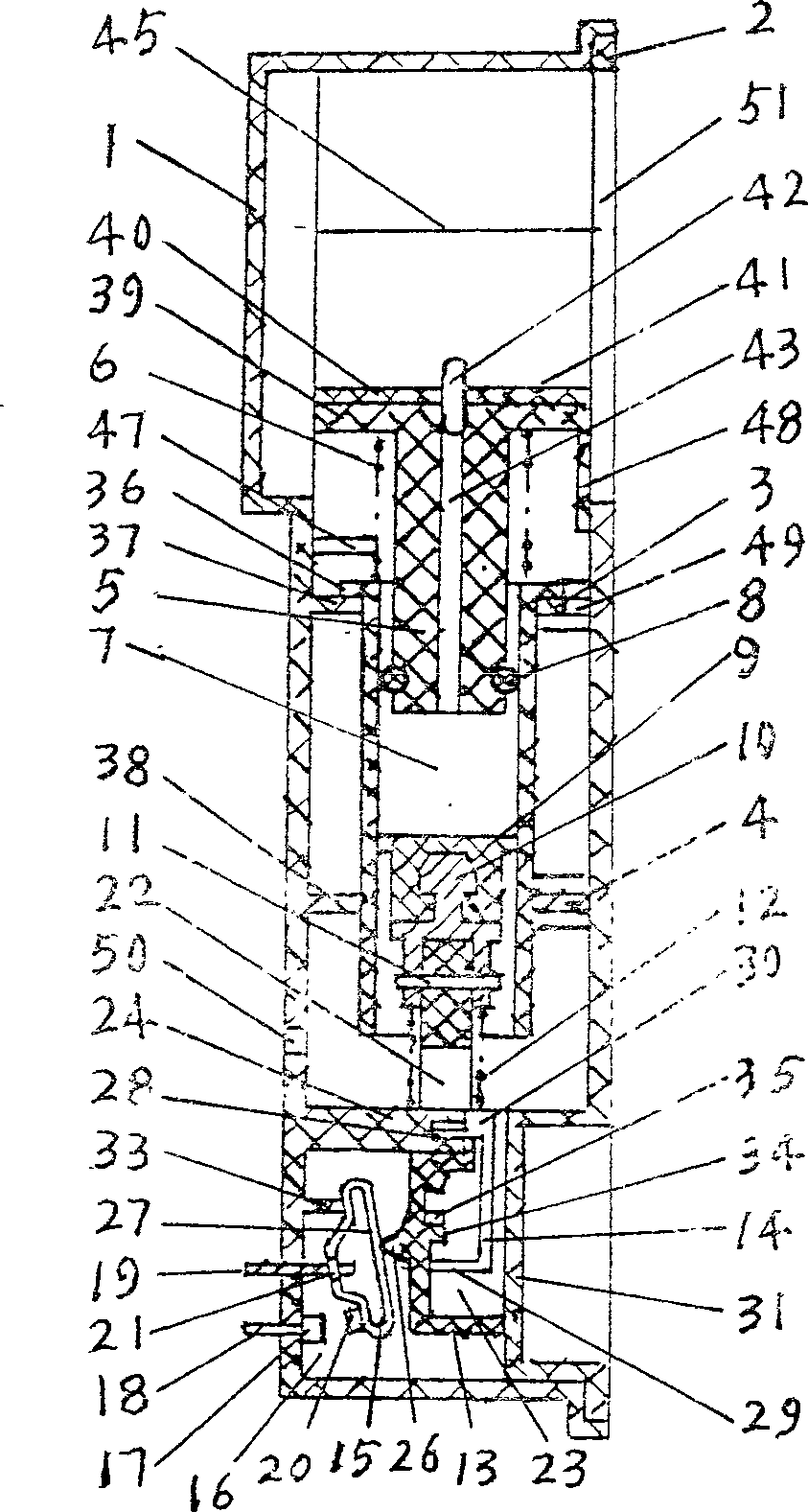
[0032] This embodiment will describe a full-control switch of the present invention provided with an air transmission cavity of a cylinder piston in an operating mechanism with a single force point switch actuator. It is basically a switch equipped with an air transmission cavity in the operating mechanism of a commonly used push switch. When describing the direction below, the figure 1 looking at figure 2 Look to the right to set the direction. Such as figure 1As shown in -4, the housing of the switch in this embodiment is made up of a shell box 1, a shell cover 2, an upper clamp 3 and a lower clamp 4. The operating mechanism of the switch is composed of active piston 5, spring 6, cylinder 7, sealing ring 8, driven piston 9, connector 10, pin 11, spring 12, rail rod 13, rail clamp 14, bullet frame 15 and other parts . Among them, the active piston 5, the spring 6, the cylinder 7, the sealing ring 8, and the driven piston 9 are installed in the casing and the spring 12 p...
Embodiment 2
[0037] This embodiment is a full-control switch of the present invention made of a commonly used push switch equipped with an air transmission cavity of an elastic airbag. Such as Figure 5 , Figure 6 As shown, push switch 53 can see its button 54, rail bar 13, spring 12, housing 55, movable contact terminal 19, static contact terminal 18 etc. from the outside. The structure and principle of the operating mechanism of the push switch 53 are basically the same as those described in Embodiment 1. Button 54 is enclosed within on the upper end of rail bar 13, and it is single acting force point switch starter, and it cooperates with moving contact transmission. The cylinder shell 56 is in the shape of a platform, and its upper cylinder 57 is large, the lower cylinder 58 is small, and the upper end has reversed sides 59 . Two screws 60 pass through the hole at the bottom of the shell 56 and are tightened in the mounting screw holes of the push switch 53, so that the push switch...
Embodiment 3
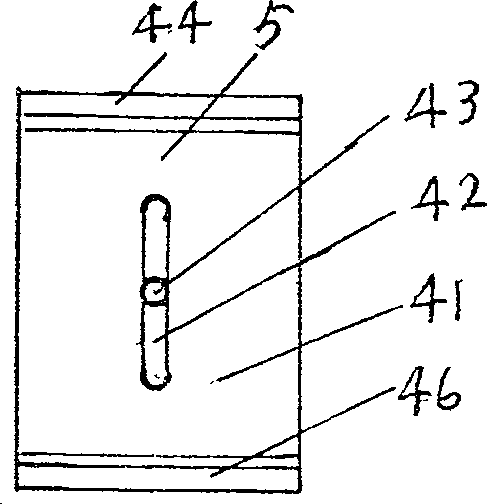
[0041] This embodiment will describe a semi-controlled switch of the present invention in which an air transmission cavity of a cylinder piston is arranged in an operating mechanism with a double-action point switch actuator. Such as Figure 7 As shown, the thick solid line with hatching in the figure indicates the shell or the parts embedded in the shell, and the shell is made of insulating material. The air transmission chamber consists of a cylinder 5, a piston 9, a spring 6, and a spring 79 installed behind the housing, wherein the cylinder 5 is the driving end, the piston 9 is the driven end, the spring 6 is the reset element of the active end, and the spring 79 is the driven end. terminal reset element. The upper part of the cylinder 5 is a pressing surface part 39, on which there is a concave arc-shaped pressing surface 41, and a plurality of air holes 42 are opened on the pressing surface 41, and the air holes 42 communicate with the inside of the cylinder 5, that is,...
PUM
 Abstract
Description
Claims
Application Information