
Luminous sign panel

A technology of signs and signs, applied in the field of luminous signs, can solve the problem of low luminous brightness of luminous signs, and achieve the effect of increasing the brightness of light

Inactive Publication Date: 2009-06-17
HONG FU JIN PRECISION IND (SHENZHEN) CO LTD +1
View PDF6 Cites 0 Cited by
  • Summary
  • Abstract
  • Description
  • Claims
  • Application Information

AI Technical Summary

Problems solved by technology

[0006] In order to overcome the shortcomings of the luminous signboards in the prior art that the luminous brightness is not high, the present invention provides a luminous signboard with high luminous brightness

Method used


Image

  • Luminous sign panel
  • Luminous sign panel
  • Luminous sign panel

Examples


Embodiment Construction

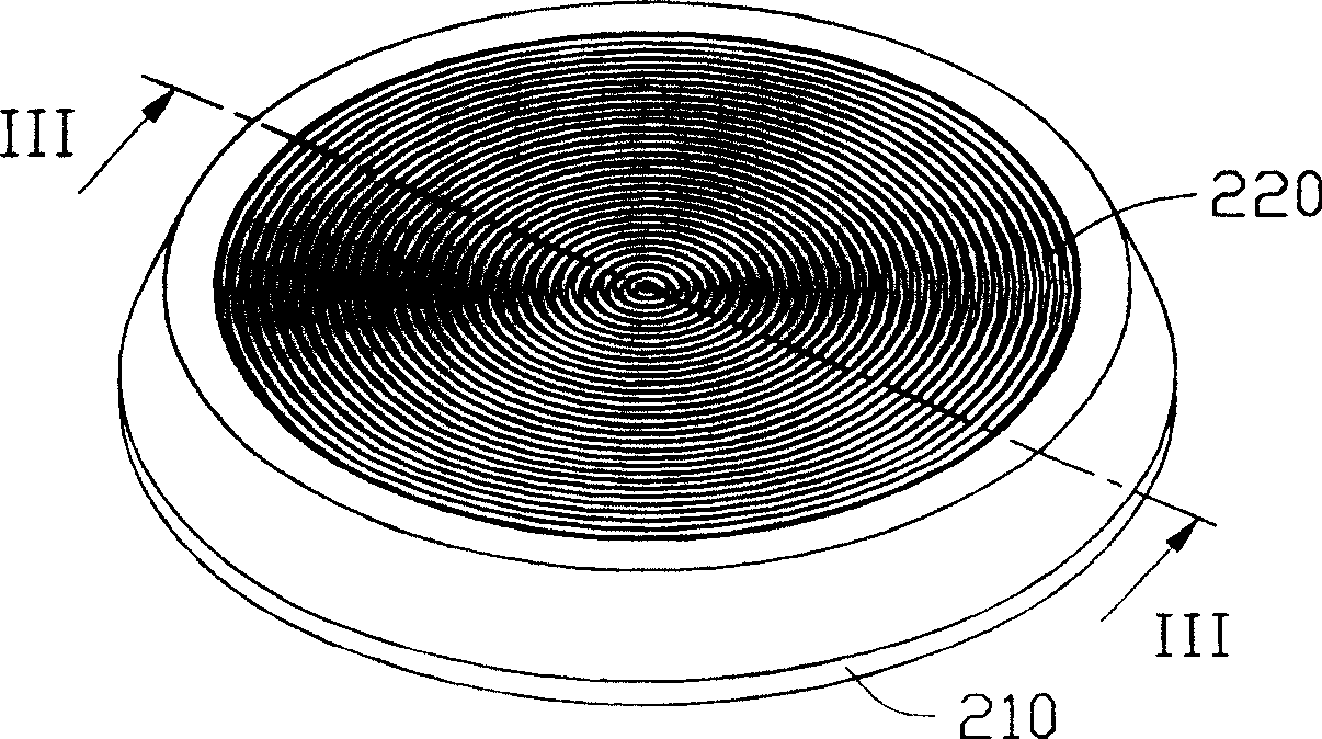
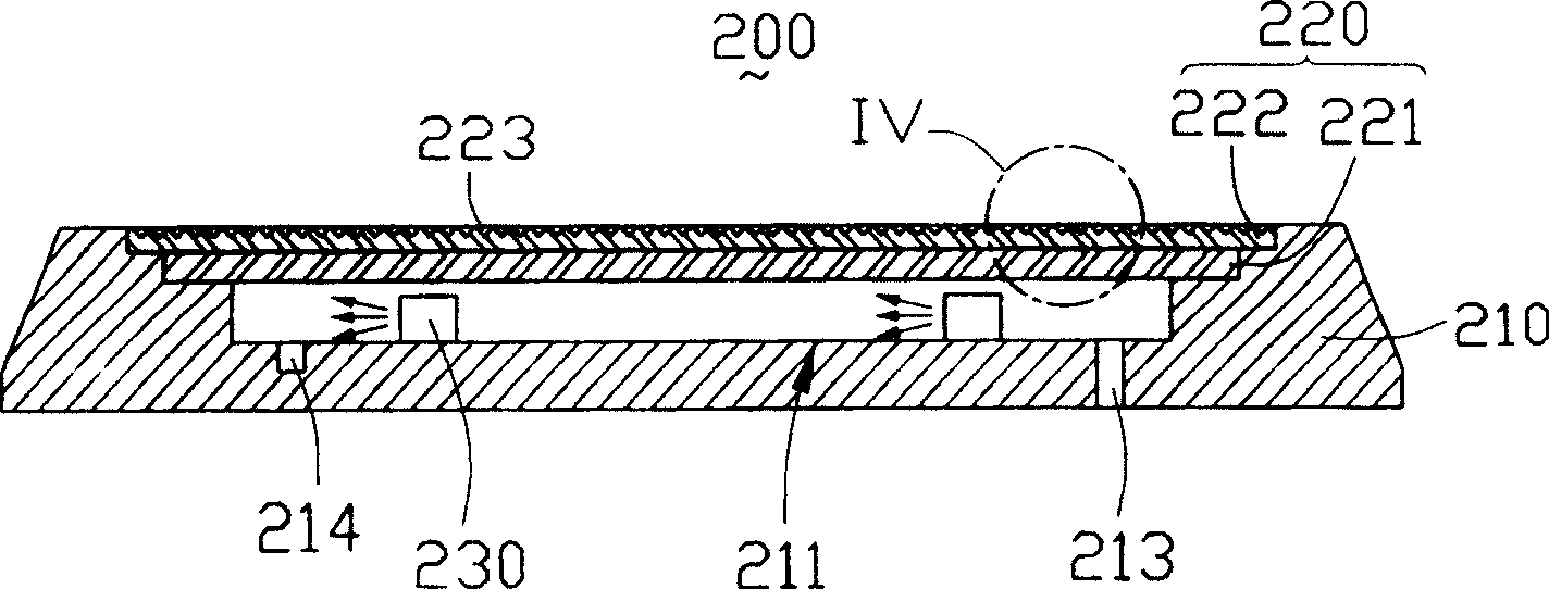
[0016] see figure 2 with image 3 , is a perspective view and a cross-sectional view of the first embodiment of the luminous signboard of the present invention. The luminous sign board 200 includes a base 210 , a sign panel 220 and a light emitting device 230 . The light emitting device 230 is arranged on the base 210, and the base 210 is provided with an annular groove 214 for accommodating a power supply wire (not shown) for driving the light emitting device 230, and a point of the annular groove 214 is provided with a through hole. The hole 213 is provided, so that the power supply wire is led out of the base 210 through the through hole 213 . The light emitting device 230 is a plurality of light emitting diodes, which can be symmetrically disposed on the inner surface 211 of the base 210 along the annular groove 214 .

[0017] The logo panel 220 includes a logo pattern panel 221 and a protective layer 222. The logo pattern panel 221 can be made of a soft material, whic...


PUM


Abstract

The present invention provides one kind of light emitting mark board with high brightness. The light emitting mark board includes one light emitting device, one base and one mark panel. The light emitting device includes one light source, the base has one inner surface with annular notch, and the mark panel includes one mark pattern panel and one protecting layer. The light emitting device is located in the inner surface of the base, and the protecting layer has several notches in the light outgoing surface.

Description

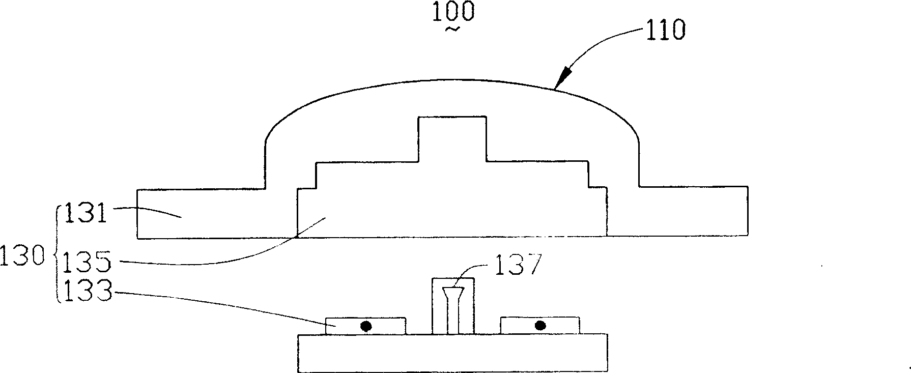
【Technical field】 [0001] The invention relates to a luminous sign board. 【Background technique】 [0002] At present, luminous signs (LOGO), such as traffic display boards, billboards, etc., are increasingly used in public places and commercially. , most of them have problems such as poor display effect. [0003] In order to realize the clear display and easy identification of markers, and the full use of the light emitted by the light-emitting device to avoid energy loss, the light-emitting device of the luminous sign board should have the ability to generate high frontal light intensity and make full use of the emitted light. Features are good. [0004] A kind of prior art luminescent sign board can refer to the U.S. Patent No. 6,174,075 of announcement on January 16, 2001, as figure 1 As shown, the light-emitting signboard 100 includes a light-emitting device 130 and a sign panel 110. The light-emitting device 130 includes a PVC (PolyvinylChloride, polyvinyl chloride) b...

Claims


Application Information

Patent Timeline
Patent Type & Authority Patents(China)
IPC IPC(8): G09F13/04
Inventor 蔡明江李俊佑江宗韦
Owner HONG FU JIN PRECISION IND (SHENZHEN) CO LTD
Learn More