

Vehicle brace bar
A vehicle, contour technology, applied in the direction of vehicle components, axles, wheels, etc.
- Summary
- Abstract
- Description
- Claims
- Application Information
AI Technical Summary
Problems solved by technology
Method used
Image

Examples
Embodiment Construction
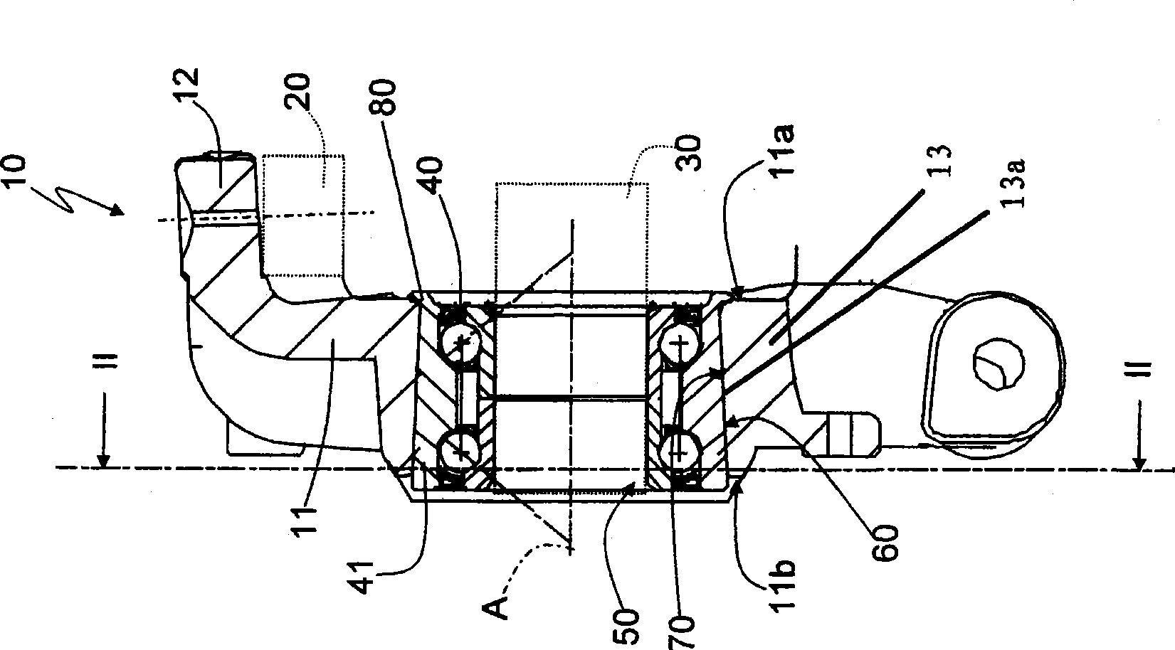
[0009] refer to figure 1 , The reference numeral 10 represents the whole vehicle strut.
[0010] The strut 10 is adapted to be placed between a suspension, shown schematically and referenced 20 , and a half shaft, shown schematically and referenced 30 .
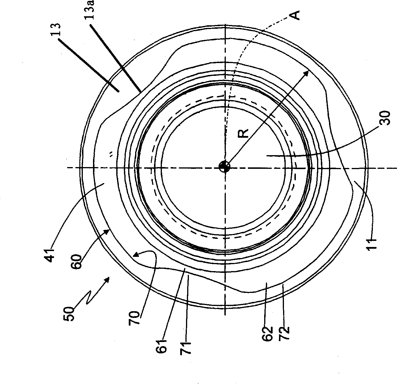
[0011] The strut 10 comprises a central body 11, a connecting arm 12 for connection with the suspension 20, and a through housing 13 formed through the central body 11 along a longitudinal axis for accommodating a Rolling contact bearing 40 between strut 10 and half shaft 30 .
[0012] The arm 12 extends from the side surface 11a of the central body 11 itself in a direction substantially transverse to the central body 11 and through the housing 13 on one side through the surface 11a itself and on the other side substantially parallel to the surface 11 and transverse to the The surface 11b of the axis A is axially defined.
[0013] Finally, the strut 10 includes a joint device 50, which is placed between the bearing 40 and ...
PUM
 Abstract
Description
Claims
Application Information