
Rolling mill control device and method

A technology for control devices and rolling mills, applied in the direction of rolling mill control devices, metal rolling, metal rolling, etc., can solve problems such as the distance of rolling mills becoming longer and control lag, and achieve the effect of reducing influence and avoiding control lag

Inactive Publication Date: 2009-07-22
HITACHI LTD
View PDF9 Cites 0 Cited by
  • Summary
  • Abstract
  • Description
  • Claims
  • Application Information

AI Technical Summary

Problems solved by technology

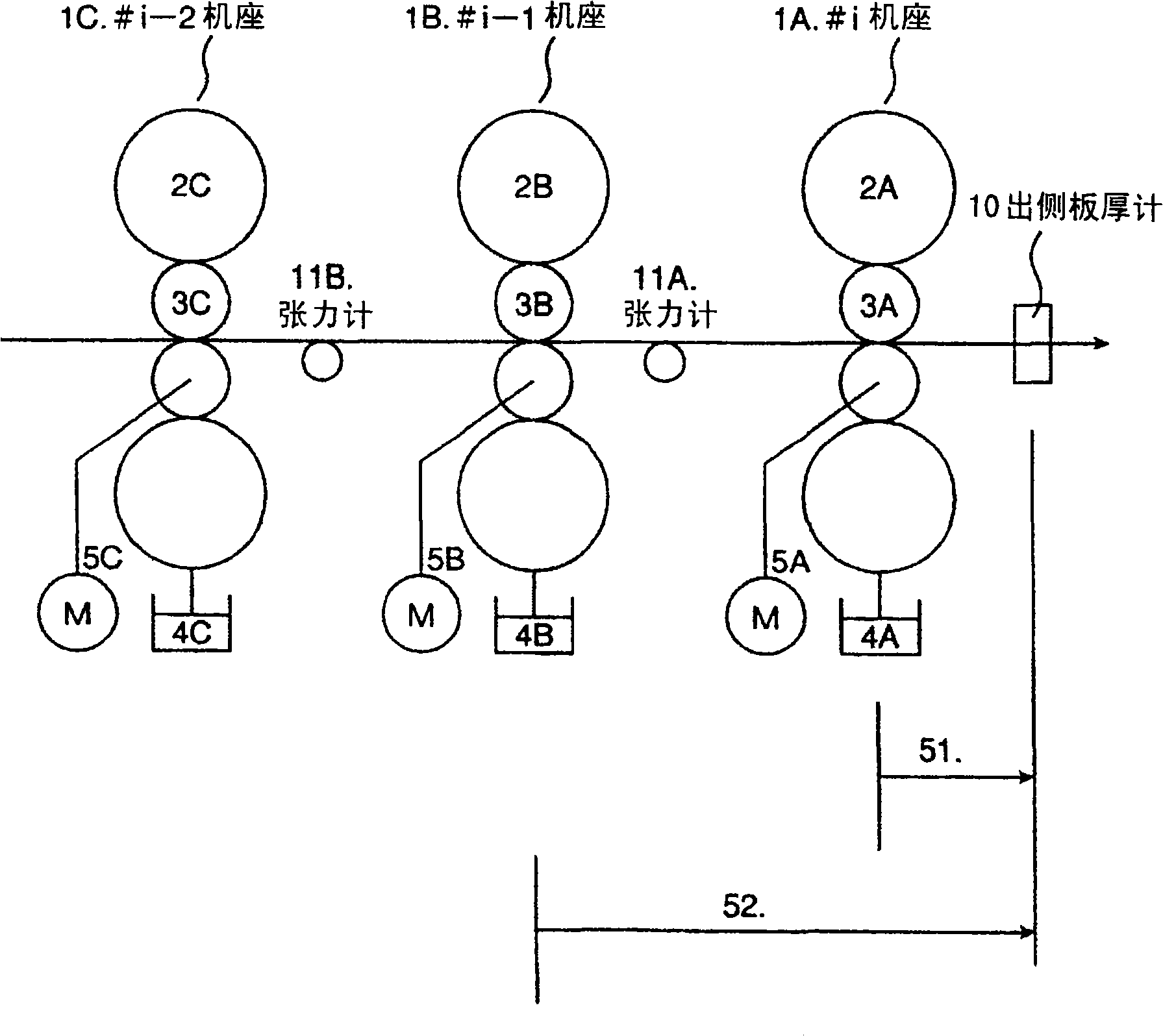
As a result, the distance from the measuring device to the target rolling mill becomes unavoidably long and control lags.

Method used


Image

  • Rolling mill control device and method
  • Rolling mill control device and method
  • Rolling mill control device and method

Examples


Embodiment Construction

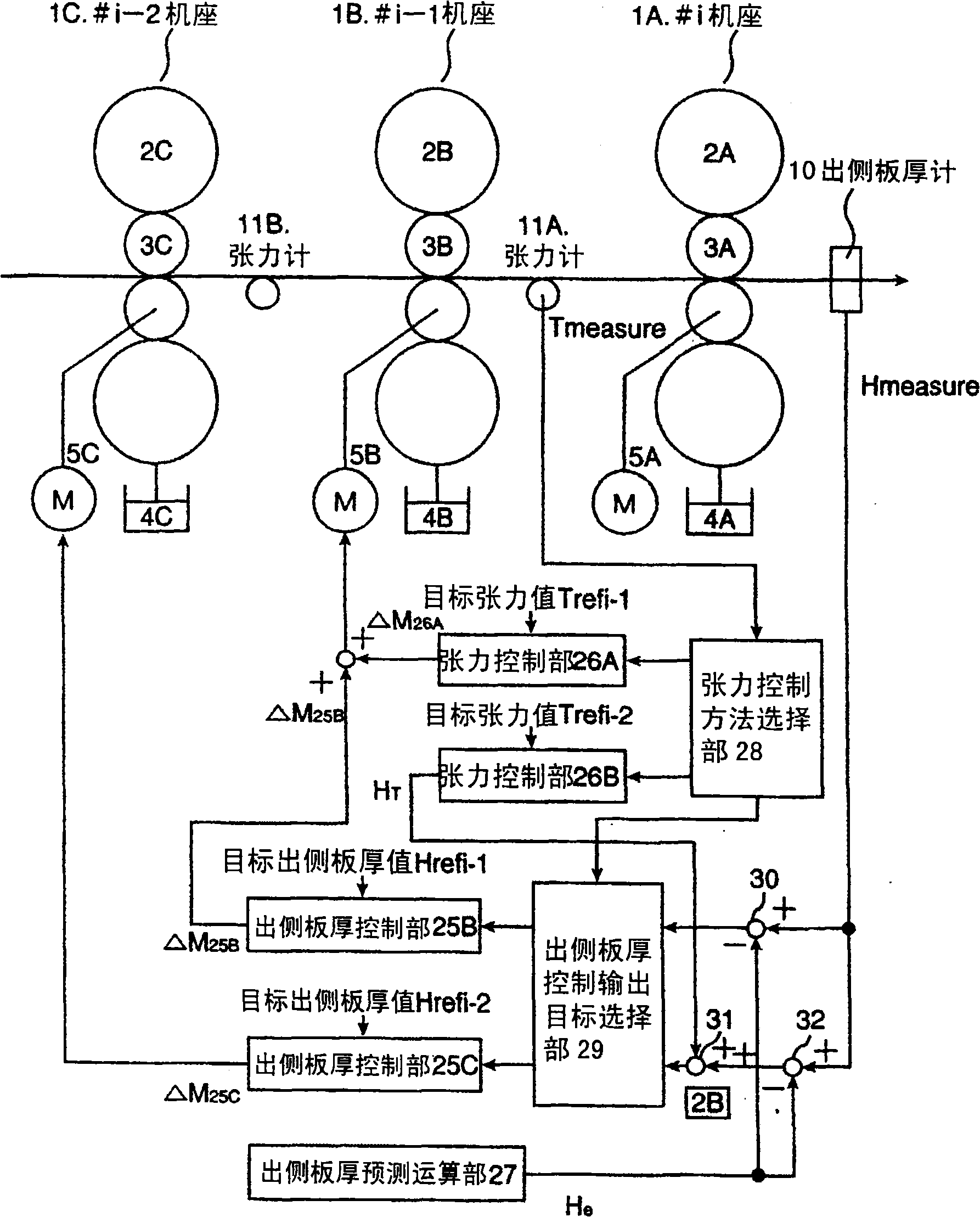
[0018] Hereinafter, the best mode for carrying out the present invention will be described with reference to the drawings. In order to facilitate understanding of the concept of the present invention, a reference example will be described first, and then the basic idea will be described.

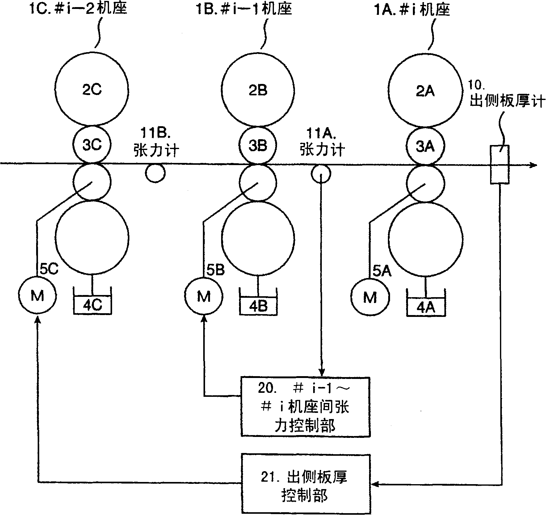
[0019] First, a reference example will be described. The plate thickness control and tension control of the tandem cold rolling mill using passivated rolls with high friction coefficient as the final stand are as follows: figure 2 structure shown. Each stand 1A (#i stand) to 1C (#i-2 stand) is composed of work rolls 3A, 3B, 3C and backup rolls 2A, 2B, 2C. In the tandem rolling mill composed of i-stands, the rolling mill has i-stands. Each stand is composed of the following: backup roll 2 (the general designation of symbols 2A, 2B, and 2C is denoted as symbol 2); work roll 3 (the general designation of symbols 3A, 3B, and 3C is denoted as symbol 3); and for controlling the work roll 3 Th...


PUM


Abstract

In the continuous cold rolling mill with passivated rolls used in the final stand, there is interference between the tension control of the entry side of the final stand and the thickness control of the exit side with the speed of the final stand (-1) as the control operation end, and the exit side plate Thick control's response lag problem. For this reason, by changing the target value of the control plate thickness, the two exit-side plate thickness controls with the speed of the (final base-1) base and the speed of the (final base-2) base as the control operation end interfere, And through the tension control of the entry side of the final frame, the tension control of the entry side of the final frame will not interfere with the thickness control of the exit side with the speed of (final frame-1) frame as the control operation end. In addition, by predicting the change in the thickness of the exit side from the control output of the exit thickness control, and using this method to correct the measured value of the exit thickness used in the exit thickness control, the performance of the exit thickness control itself is improved. response.

Description

technical field [0001] The invention relates to a control device of a rolling mill and a control method of the rolling mill. Background technique [0002] Generally, in rolling control, a plurality of physical states indicating the rolling state are controlled to be kept predetermined. The physical state includes plate thickness and tension. Regarding the plate thickness, in order to make the plate thickness after rolling reach the target plate thickness, a plate thickness gauge is arranged on the exit side of the rolling mill, and the deviation between the output side plate thickness gauge and the target plate thickness is calculated, and the speed of the rolling mill is controlled. and other control objects so that the deviation is close to zero. Similarly, for tension, in order to achieve the target tension, install a tensiometer on the entry side of the rolling mill, find the deviation between the output of the tensiometer and the target thickness, and control the spee...

Claims


Application Information

Patent Timeline
Patent Type & Authority Patents(China)
IPC IPC(8): B21B37/00B21B37/16B21B37/48B21B37/52
Inventor 服部哲福地裕
Owner HITACHI LTD
Learn More