Electrical connector for printed circuit board

A connector and contact arm technology, applied in the direction of connection, circuit, connection of four or more poles, etc., can solve the problems of contamination of contact parts, tin absorption of flux or flux, etc., to achieve the effect of efficient manufacturing process

Inactive Publication Date: 2009-07-22
MOLEX INC
View PDF6 Cites 0 Cited by
  • Summary
  • Abstract
  • Description
  • Claims
  • Application Information

AI Technical Summary

Problems solved by technology

[0007] In addition, prior art terminal receiving cavities or mounting channels formed in the housing create other problems, such as when soldering the connector to the circuit board, through the gap between the terminal and its cavity or channel, possible Tin-attracting action of solder or flux, which may cause contamination of contact parts mated with terminals of mating connectors

Method used


Image

  • Electrical connector for printed circuit board
  • Electrical connector for printed circuit board
  • Electrical connector for printed circuit board

Examples


Embodiment Construction

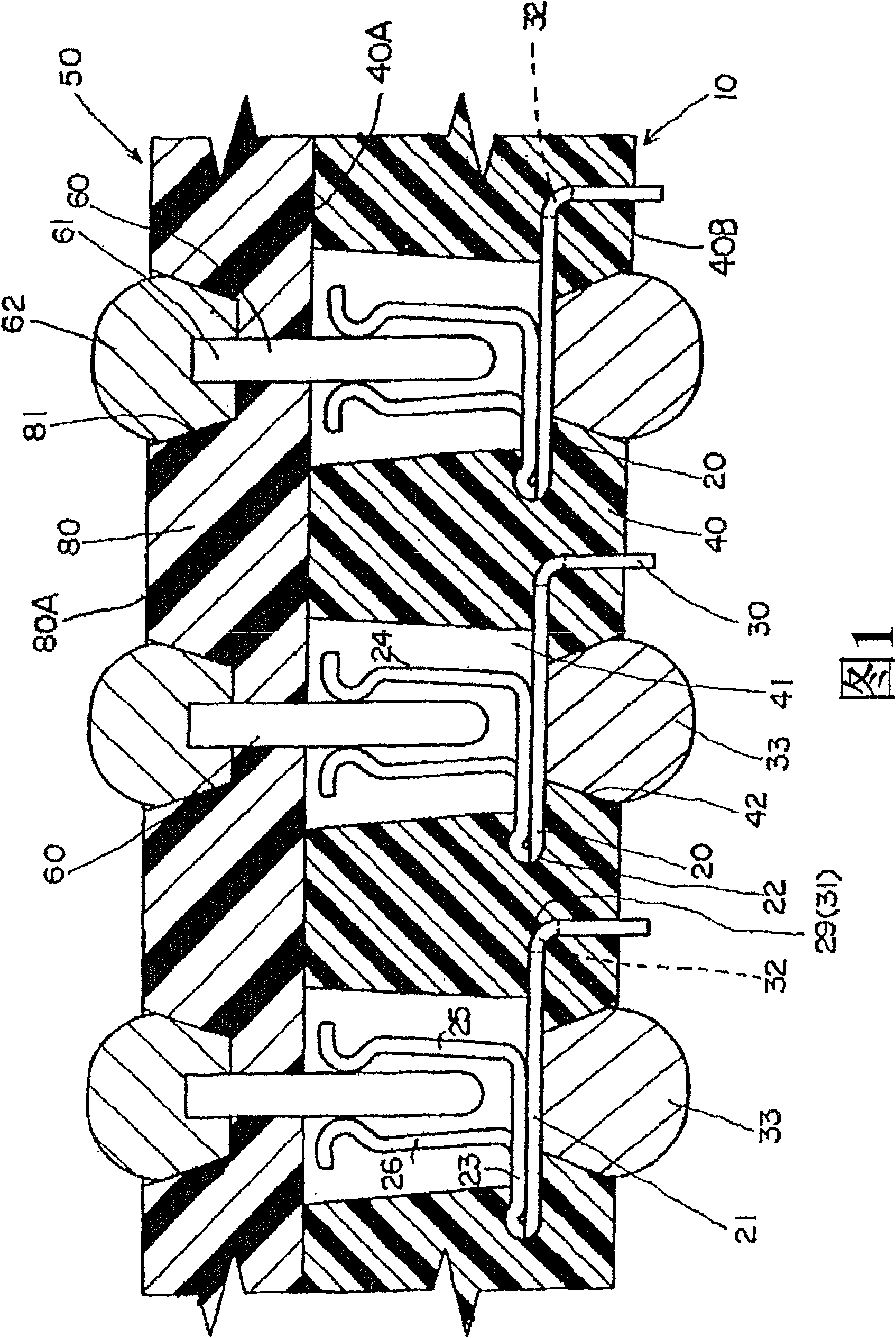
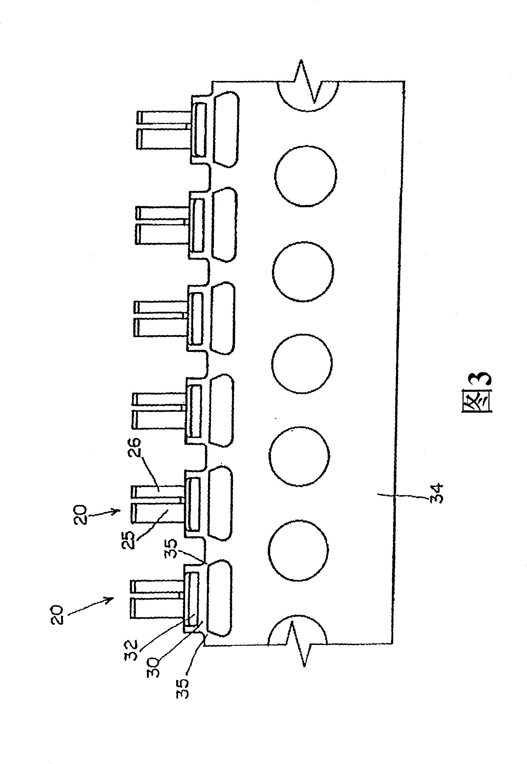
[0032] Referring to FIG. 1 , there is shown an electrical connector assembly comprising a connector 10 and a mating electrical connector 50 , both of which can be mated together. The connector 10 includes a plurality of terminals 20 arranged in a side-by-side sequence at a predetermined pitch, and a dielectric housing 40 is molded on the terminals 20, preferably by overmolding. The mating connector 50 includes a plurality of contact pins 60 arranged side by side in a one-to-one relationship corresponding to the terminals 20 on the connector of the present invention, and a dielectric housing 80 is overmolded on the contact pins 60 . As shown in FIG. 1 , the terminals 20 and the contact pins 60 are arranged at predetermined pitches in a right-to-left direction, and further, they are arranged in a direction perpendicular to the paper plane of FIG. 1 .

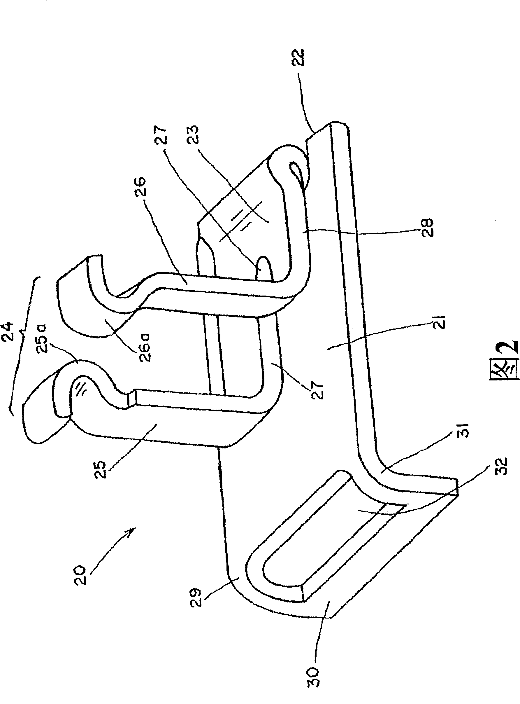
[0033] Each terminal 20 of the connector 20 is preferably produced by pressing and forming it from sheet metal in the shape sho...


PUM


Abstract

An electrical connector 10 for mounting to a printed circuit board, comprises a dielectric housing 40 and a plurality of terminals 20 arranged side by side at the predetermined pitch. Each terminal 20 includes a flat base portion 21, a pair 24 of contact members formed from a continuous folded-back portion 23 that is folded back to one side of the flat base portion 21, and a carrier coupling section 30 that is bent at substantially right angle to the opposite side of the flat base portion 21. The housing 40 holds the terminals 20 by an over-molding of the housing around the flat base portions 21 of the terminals 20 to form a generally flat plate-like housing. The pair 24 of contact members of the terminal 20 extends toward one surface 40A of the dielectric housing 40 and the carrier coupling section 30 extends toward the other surface 40B of the housing 40.

Description

technical field [0001] The present invention relates generally to an electrical connector suitable for mounting to a printed circuit board, and in particular to a connector for use in solder ball grid array (BGA) applications. Background technique [0002] In the past, an electrical connector of this type is known that includes a dielectric housing and a plurality of terminals. 6 and 7 show examples of such prior art connectors, and specifically, FIG. 6 shows one terminal 100 of the connector. A plurality of such terminals 100 are mounted or press-fitted to the housing 200 ( FIG. 7 ) to complete the electrical connector 300 . Although only one terminal 100 is shown in the drawing, actually a plurality of such terminals 100 are arranged side by side at a predetermined pitch. 6, the terminal 100 includes a pair of contact members, or arms 101, a press fit portion 102 formed at the base of the contact members, and a fixed portion formed adjacent to the press fit portion for c...

Claims


Application Information

Patent Timeline
Patent Type & Authority Patents(China)
IPC IPC(8): H01R13/405H01R12/22H01R24/00H01R43/02H01R107/00
CPCH01R12/716H01R13/405H01R43/0256
Inventor 野田敦人手塚宣弥
Owner MOLEX INC
Why Eureka
Try Eureka