
Hydraulic ship lift

A ship lift and hydraulic lifting technology, which is applied in the vertical lifting of ship machinery, ship lifting devices, buildings, etc., can solve the problems of difficult manufacturing, irreparable, difficult realization and maintenance, etc., so as to reduce the design strength requirements and prevent deviation. Load tilt phenomenon, enhance the effect of self-recovery function

Inactive Publication Date: 2009-07-29
TAIYUAN UNIV OF TECH
View PDF7 Cites 0 Cited by
  • Summary
  • Abstract
  • Description
  • Claims
  • Application Information

AI Technical Summary

Problems solved by technology

[0002] CN 1532345A discloses "A New Ship Lift", which utilizes the brackets on both sides to form a circular ladder, so that the ship carrier or the ship carrier box can be lifted step by step in a step-by-step cycle. This ship lift exists The following problems: complex system structure, scattered institutions, high failure rate, poor security, difficult to implement and maintain
This kind of ship lift requires the brackets on both sides to form a circular ladder shape, and its structure is complex and difficult to manufacture; because it adopts a step-up work process in which the ship carrier or the ship carrier is arranged in a stepwise cycle, it will inevitably cause the ship carrier Or the stress point of the ship-bearing box is constantly changing at the working point of the support, which is prone to eccentric loads, causing major failures, and the system has a relatively large risk; The connection process reduces the operating efficiency; the horizontal pin structure is adopted between the ship carrier or the ship carrier and the hydraulic cylinder, which is easily deformed by the gravity of the ship carrier or ship carrier, and it is difficult to operate for a long time. Once a failure occurs, usually It cannot be repaired; during operation, if one of the hydraulic cylinders in a group fails, it will cause the system to crash, and the safety is poor; there is no protection against fluctuations in the liquid surface and waterproof surface, and if the lifting speed is too high, the system will be unstable, and the safety is poor

Method used


Image

  • Hydraulic ship lift
  • Hydraulic ship lift
  • Hydraulic ship lift

Examples


Embodiment Construction

[0016] Hereinafter, the present invention will be described in detail through preferred embodiments with reference to the accompanying drawings.

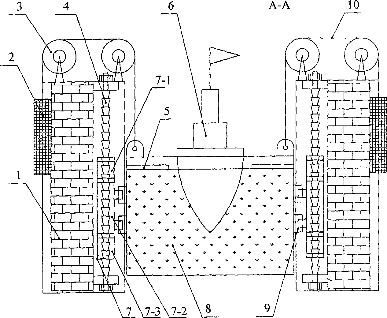
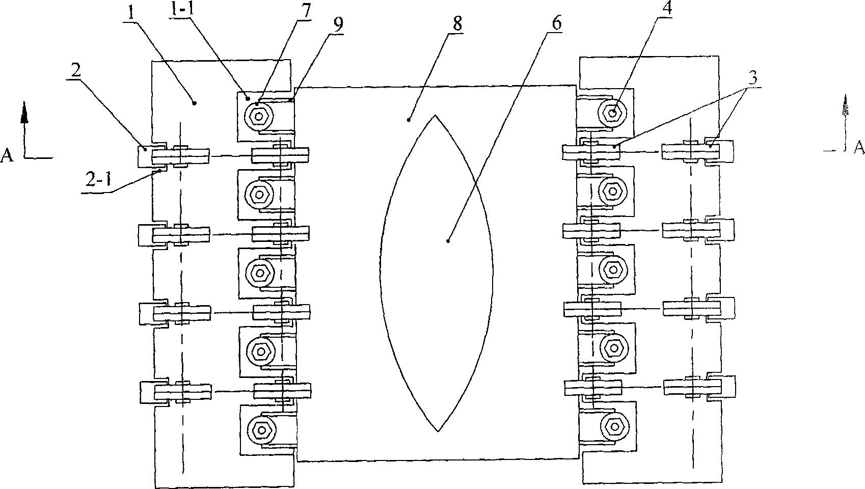
[0017] Such as figure 1 , 2 As shown, a hydraulic ship lift includes: a ship lift box 8 driven by a drive mechanism fixed on a dam body 1, and a counterweight 2 connected to the ship lift box through a fixed pulley block 3 installed on the dam body 1 , The driving mechanism is a hydraulic lifting manipulator 7 and its hydraulic control system which are evenly distributed on both sides of the ship lift box 8 and sleeved on the bamboo-jointed propulsion column 4 fixed to the dam body 1, and the hydraulic lifting manipulator 7 and The lift box 8 is connected by a hand 9 driven by a hydraulic cylinder.

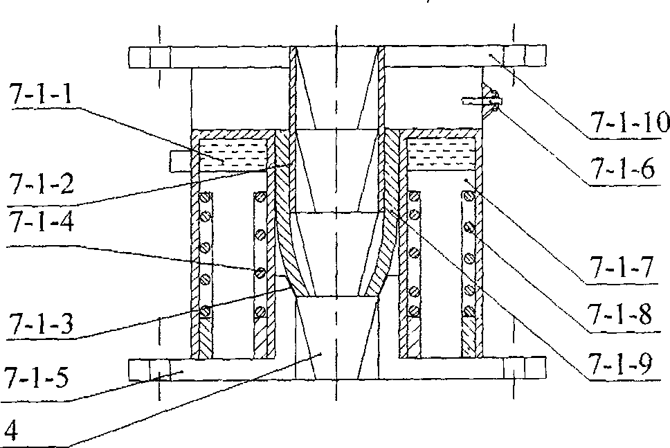
[0018] Such as image 3 , 4 As shown, the hydraulic lifting manipulator 7 is composed of an upper clamping self-locking section 7-1, a middle lifting section 7-2, and a lower clamping self-locking section 7-3. The upper clamping self-locki...


PUM


Abstract

The invention discloses a hydraulic ship lift, which relates to a vertical ship lift. The ship lift in the prior art has complex structure, high failure rate and poor safety. The driving mechanism of the present invention is a hydraulic lifting manipulator evenly distributed on both sides of the ship lift box, which is connected with the handle of the ship lift box driven by a hydraulic cylinder. The hydraulic lifting manipulator is used to realize the self-lifting and self-locking of the hydraulic cylinder, and the reciprocating movement, just like the process of lifting heavy objects with human hands, realizes the lifting and landing of the ship lift. Through its reciprocating motion, a single short-stroke hydraulic cylinder can realize the hydraulic lifting function of large-distance operation; at the same time, it can be flexibly combined to realize the function of the ship lift to transport ships. The invention has the advantages of simple structure, low failure rate, safe and reliable equipment operation, strong flexibility, self-recovery function under partial failure, high operation efficiency, etc., and can be used for lifting ships at high dams.

Description

Technical field [0001] The invention relates to a vertical ship lift, especially a hydraulic ship lift. Background technique [0002] CN 1532345A discloses "a new kind of ship lift", which uses the brackets on both sides to form a circular ladder shape, so that the ship carrier or the ship container is arranged and combined step by step in a ladder cycle manner. This kind of ship lift exists The following problems: the system structure is complex, the organization is scattered, the failure rate is high, the safety is poor, and it is not easy to implement and maintain. This kind of ship lift requires the brackets on both sides to form a circular ladder shape, and its structure is complicated and difficult to manufacture; because it adopts a step-up work process in which the ship carrier or the ship carrier is arranged in a ladder cycle, it is inevitable to cause the ship carrier Or the ship carrier is constantly changing at the working stress point of the support, which is prone t...

Claims


Application Information

Patent Timeline
Patent Type & Authority Patents(China)
IPC IPC(8): E02C5/00
Inventor 李昕涛王爱玲
Owner TAIYUAN UNIV OF TECH
Learn More