

Blower for vehicle
A technology for blowers and vehicles, applied in vehicle components, heating/cooling equipment, air handling equipment, etc., can solve problems such as complex assembly work, reduced productivity, and increased manufacturing costs
- Summary
- Abstract
- Description
- Claims
- Application Information
AI Technical Summary
Problems solved by technology
Method used
Image

Examples
Embodiment Construction
[0033] Preferred embodiments of the present invention will now be described in detail with reference to the accompanying drawings.
[0034] In the present invention, descriptions of the same components and operations as those of the conventional heat exchanger will be omitted.
[0035] Figure 5 is an exploded perspective view of a blower for a vehicle according to a first preferred embodiment of the present invention, and Image 6 is a sectional view of the blower for a vehicle according to the first preferred embodiment of the present invention.
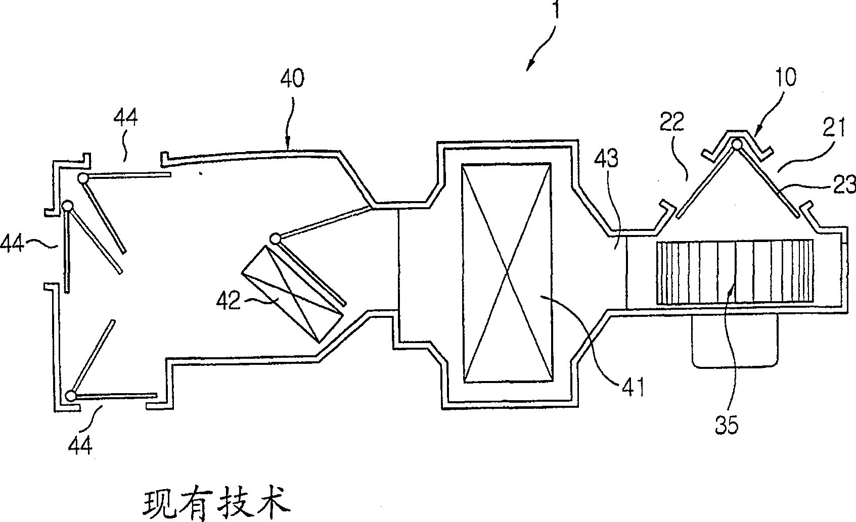
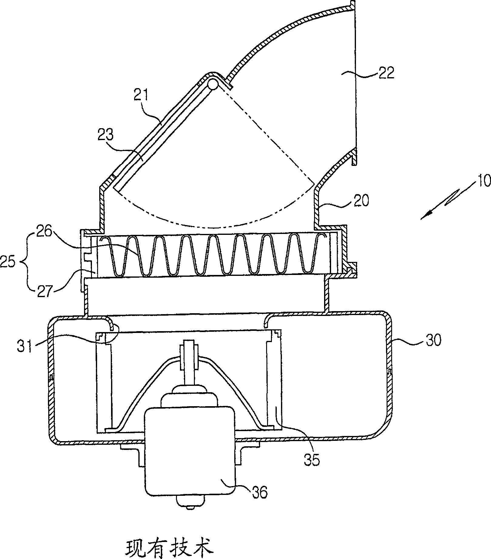
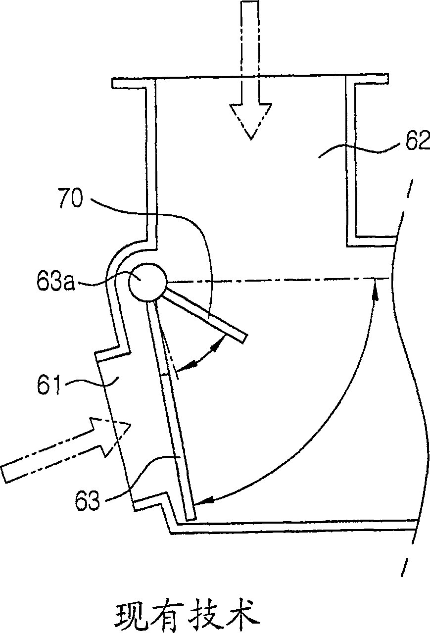
[0036] As shown in these figures, the blower 100 according to the present invention includes: an air intake duct 110 having an indoor air inlet 111 and an outdoor air inlet 112 formed on an upper portion thereof; An air switching door is rotatably installed inside the intake duct 110 for selectively opening and closing the indoor air inlet 111 and the outdoor air inlet 112; and a volute 120 installed below the intake duct 110, an...
PUM
 Abstract
Description
Claims
Application Information