Flange structure

A technology of flange components and flanges, applied in the direction of passing components, engine components, lubricating parts, etc., can solve problems such as high manufacturing costs

Active Publication Date: 2009-08-19
AICHI MASCH IND CO LTD +1
View PDF5 Cites 0 Cited by
  • Summary
  • Abstract
  • Description
  • Claims
  • Application Information

AI Technical Summary

Problems solved by technology

Therefore, this connector flange 2 needs very high manufacturing cost

Method used


Image

  • Flange structure
  • Flange structure
  • Flange structure

Examples


no. 1 approach

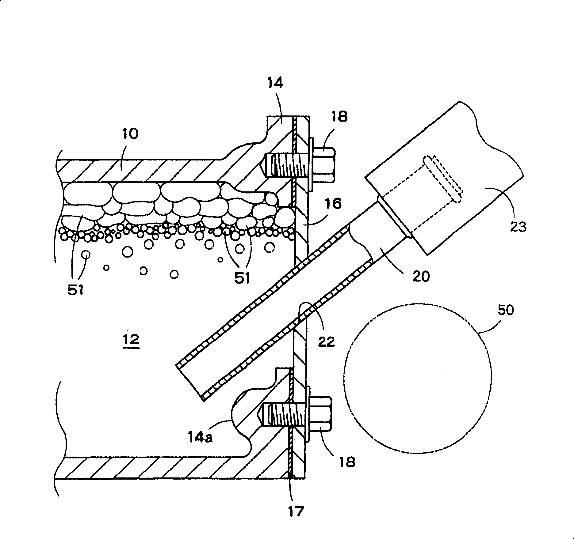
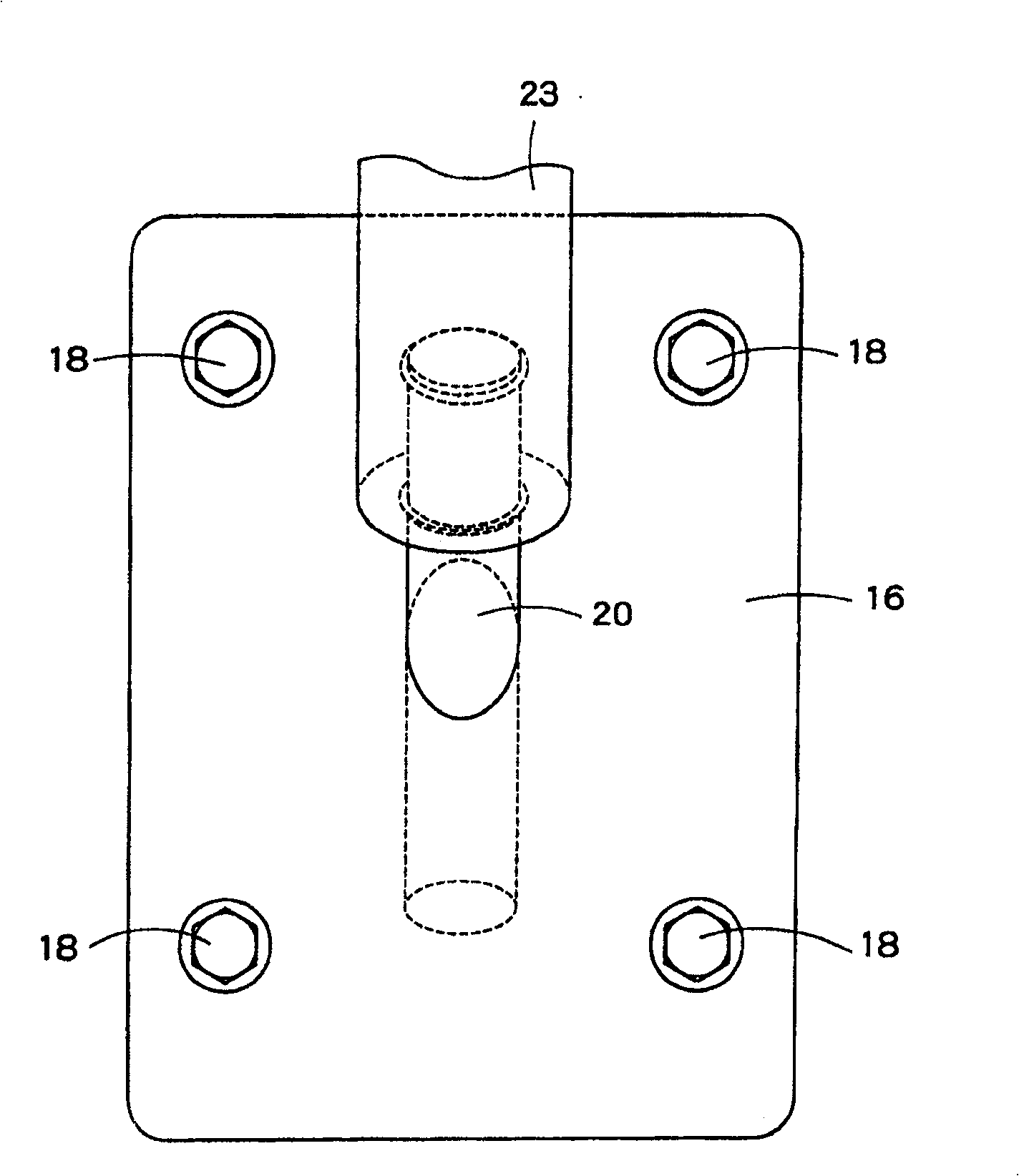
[0033] figure 1 There is shown a flange member of a first embodiment of the present invention, which is combined with a main part 10 of a heater core for heating using cooling water for cooling a motor vehicle engine, wherein the heater core is a fluid device. figure 2 yes figure 1 Front view of the flange member shown. The main part 10 of the heater core has fluid passages 12 through which cooling water flows. A flange 14 having a joint surface is formed at the free end of the main part 10 . The flange member includes a plate part 16 . and Figure 5 Unlike the conventional connector flange 2 shown provided with the boss 4, the plate member 16 is a planar member and has a uniform thickness. The plate member 16 is a metal plate whose shape corresponds to that of the flange 14 of the main part 10 . A gasket 17 is held between the joint surface of the flange 14 and the joint surface of the plate member 16 . Such as figure 2 As shown, the plate member 16 is fastened to ...

no. 2 approach

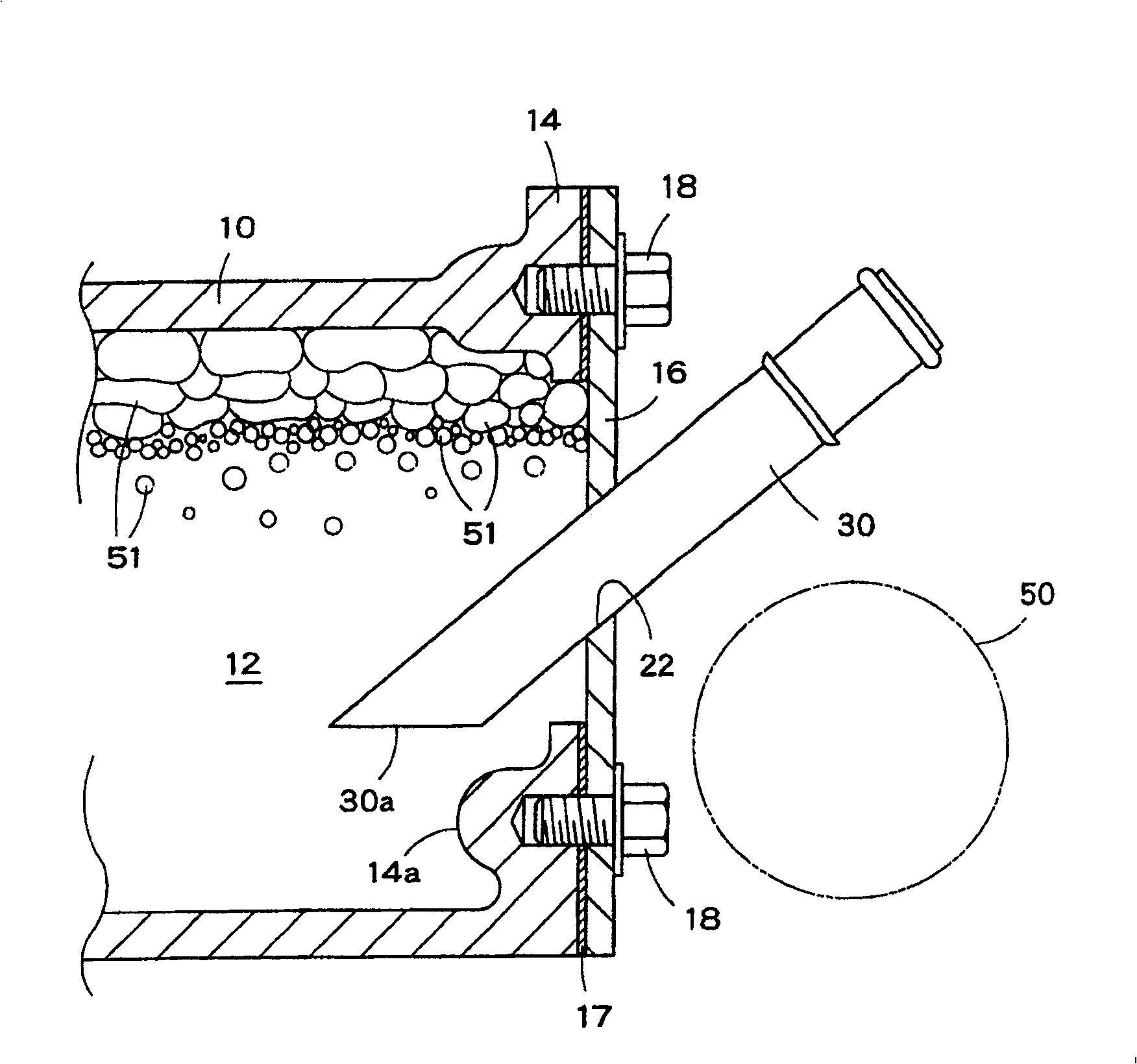
[0041] Below, refer to image 3 A flange member according to a second embodiment of the present invention will be described. The flange member in the second embodiment is similar to the flange member in the first embodiment, so the parts of the second embodiment that are the same as or corresponding to the parts of the first embodiment are given the same reference numerals and omitted. illustrate.

[0042] The flange member in the second embodiment differs from the flange member in the first embodiment only in the shape of the inner end portion of the connecting pipe 30 included therein.

[0043] Such as image 3 As shown, the connecting pipe 30 has an oblique inner end 30 a contained in a plane inclined relative to the axis of the connecting pipe 30 . The slanted inner end 30a enhances the separation of gas from liquid. The connecting pipe 30 is inserted into the main part 10 through the inclined opening 22 formed in the plate member 16 . The connecting pipe 30 is fixed ...


PUM


Abstract

The flange member of the present invention includes: a main part (10), which has a flange (14), is provided with a fluid passage (12) inside and serves as the main body of the fluid device; a plate part (16), which is installed on the main part (10) on the joint surface of the flange (14), so that the gasket (17) is held on the joint surface; the connecting pipe (20), which is inserted through the plate member (16) and enters the fluid passage (12) , and is fixed on the plate member (16) so as to extend obliquely upward and toward the outside of the plate member (16).

Description

technical field [0001] The present invention relates to flange members used in engine cooling systems and lubrication systems of motor vehicles and industrial machinery. Background technique [0002] In some cooling systems or some lubricating systems of engines, flanges commonly called connector flanges are mounted on the body of the fluid device provided with fluid passages. [0003] Such as Figure 5 As shown, a conventional connector flange 2 is mounted on a member 1 with a fluid passage 3 inside. The connector flange 2 is integrally provided with a boss 4 . The connector flange 2 is formed by casting or forging. On the boss 4, a connection pipe 5 is fixedly mounted by press-fitting. A pipe 6 is connected to the connection pipe 5 . The connector flange 2 has a joint face 7 a joined to a joint face 7 b of the member 1 . A washer 8 is held between the joint surface 7 b of the component 1 and the joint surface 7 a of the connector flange 2 fastened to the component 1 w...

Claims


Application Information

Patent Timeline
Patent Type & Authority Patents(China)
IPC IPC(8): F01P11/04F01M11/02F02N17/06F16L23/00F02N19/10F16L41/08F28F9/02
CPCF01P11/028B01D19/0042B01D19/0078F16N39/002
Inventor 羽田雅敏玉井章喜
Owner AICHI MASCH IND CO LTD
Why Eureka
Try Eureka