Method and device for balancing journal-less rotors

A technology for balancing devices and rotors, applied in static/dynamic balance testing, measuring devices, testing of machine/structural components, etc., can solve problems such as distortion of measurement results, rotor wetting, etc., and achieve the effect of high support rigidity

Inactive Publication Date: 2009-08-26
SCHENCK ROTEC GMBH
View PDF6 Cites 0 Cited by
  • Summary
  • Abstract
  • Description
  • Claims
  • Application Information

AI Technical Summary

Problems solved by technology

Illegal liquid discharge can lead to wetting of the rotor, which

Method used


Image

  • Method and device for balancing journal-less rotors
  • Method and device for balancing journal-less rotors
  • Method and device for balancing journal-less rotors

Examples


Embodiment Construction

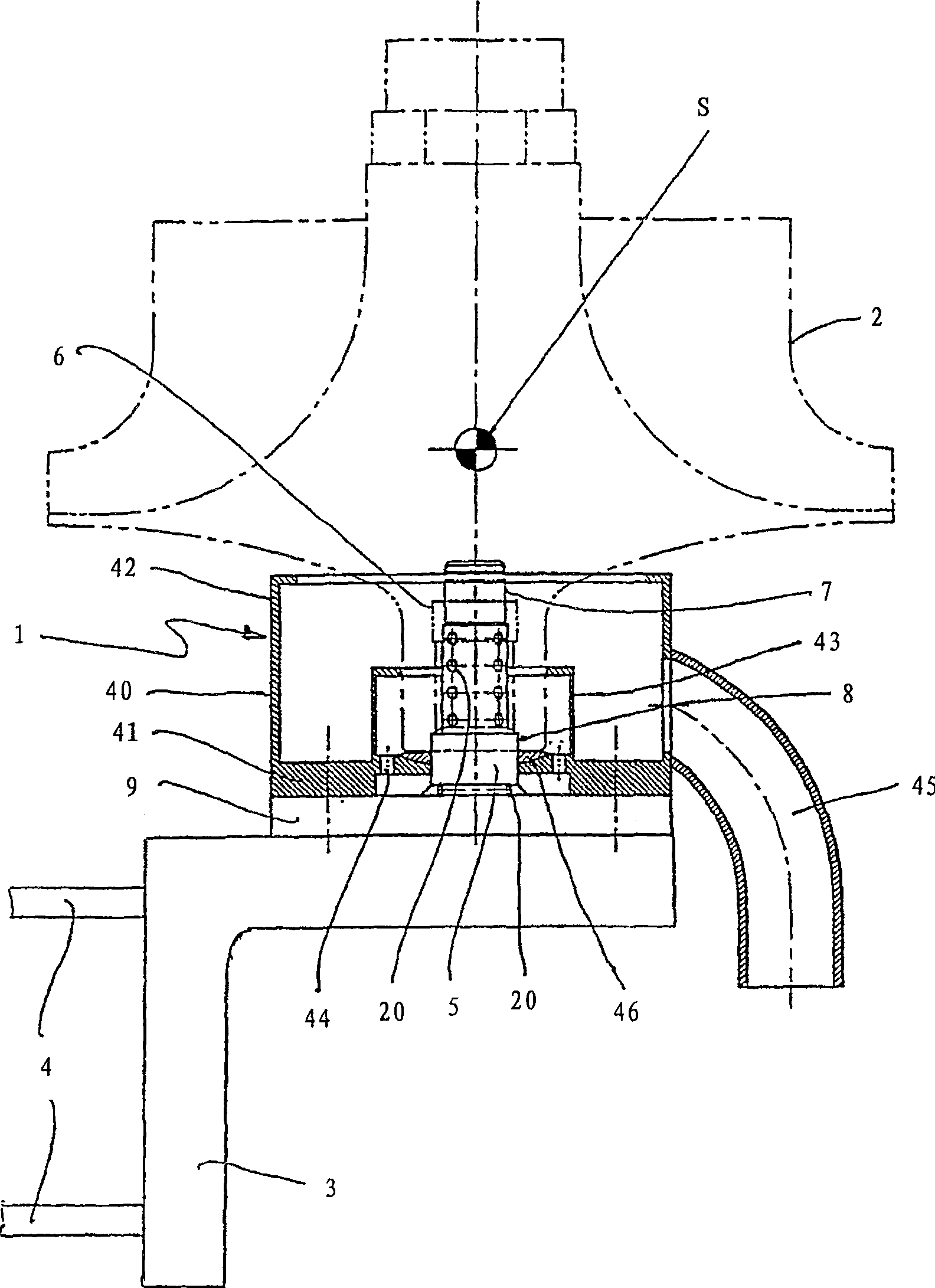
[0020] figure 1 The one shown is used for a rotor 2 to be tested (in figure 1 The support structure 1 represented by dotted line in ) is fixed on the vibrating bridge 3 of a balancing device. The vibrating bridge 3 is usually supported in a vibrating manner relative to the balancing device frame, eg on four support springs 4 (only two of which are shown in the figure). A drive mechanism (not shown in the figure) rotates the rotor 2 . The vibration of the vibrating bridge 3 caused by the unbalance is measured and the measured value of the vibration is used to determine the unbalance on the rotor 2 to be balanced.

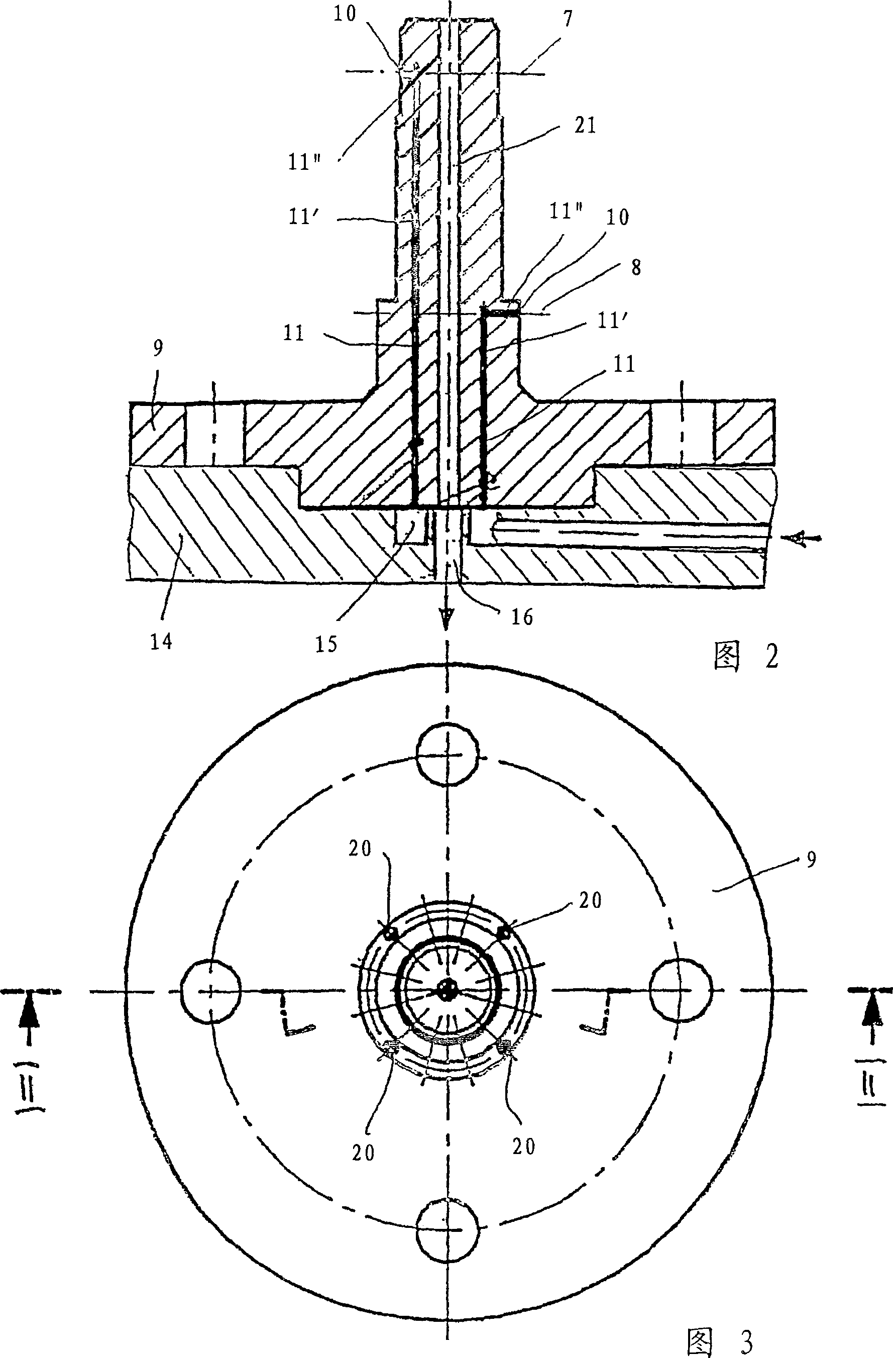
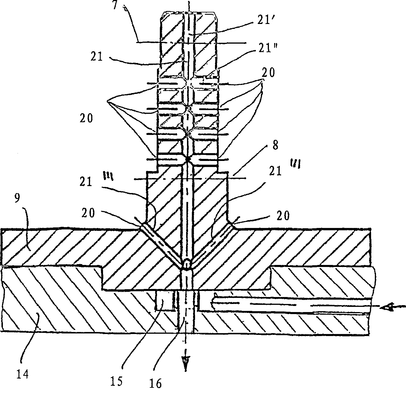
[0021] The bearing structure has a bearing spindle 5 on which the rotor 2 to be tested or balanced is rotatably mounted.

[0022] exist figure 1 In the embodiment shown, the rotor 2 has a central rotor opening 6 which does not pass through, ie a blind bore, and is supported by means of this bore on a vertically arranged bearing mandrel 5 . The center of gravity ...


PUM


Abstract

In the case of a bearing with a bearing mandrel for mounting a journal-less rotor with a bore hole in a balancing device, in which the bearing mandrel has openings for fluid to pass through, to be able to determine the imbalance of rotors with bearing possibilities on only part of their axial extent with high precision, in the bearing mandrel first openings for fluid delivery and second openings for liquid removal are provided.

Description

technical field [0001] The invention relates to a method for balancing a journalless rotor and a bearing structure with a bearing mandrel for supporting a journalless, bored rotor in a balancing device. Background technique [0002] A journaled rotor can be precisely balanced by bearing points on the journal. On the other hand, balancing rotors without their own bearing points, which are clamped on an auxiliary shaft during balancing, present great difficulties with respect to the achievable balancing accuracy. [0003] European patent application laid-open specification EP 0 104 266 A1 discloses a method for balancing a journalless rotor without an auxiliary shaft with high balancing accuracy. For this purpose, the rotor is mounted on the bearing mandrel of the balancing machine and air is used as bearing fluid which is sent between the rotor surface and the mandrel bearing surface which lie opposite each other. Inaccuracies caused by surface accuracy no longer occur, sin...

Claims


Application Information

Patent Timeline
IPC IPC(8): G01M1/04G01M1/16
CPCG01M1/04
Inventor 迪特尔·西伦
Owner SCHENCK ROTEC GMBH
Why Eureka
Try Eureka