Gain compensating method for flaw detector

A gain compensation and flaw detector technology, which is applied in the direction of processing the response signal of detection, can solve the problems of complicated circuits, adjustment of components such as potentiometers, and complicated circuits, and achieves accurate dB value control, gain compensation, and gain control. Effect

Inactive Publication Date: 2009-09-02
GUANGDONG GOWORLD
View PDF7 Cites 2 Cited by
  • Summary
  • Abstract
  • Description
  • Claims
  • Application Information

AI Technical Summary

Problems solved by technology

[0005] 1. The gain can only be controlled according to the same curve rule, that is, there are only two stages of gain. If you want to emphasize the gain of a certain depth range, the circuit will be much more complicated, difficult to implement, and the cost is also high
[0006] 2. If there are multiple probes, each probe is a channel, and each channel has its own control requirements, the circuit becomes more complicated and requires many potentiometers, further increasing the cost of the circuit
[0007] 3. In the actual use process, due to the difficulty of adjusting the potentiometer and other components, it is impossible to modify the parameters at any time, so it cannot meet the needs of use

Method used


Image

  • Gain compensating method for flaw detector
  • Gain compensating method for flaw detector
  • Gain compensating method for flaw detector

Examples


Embodiment Construction

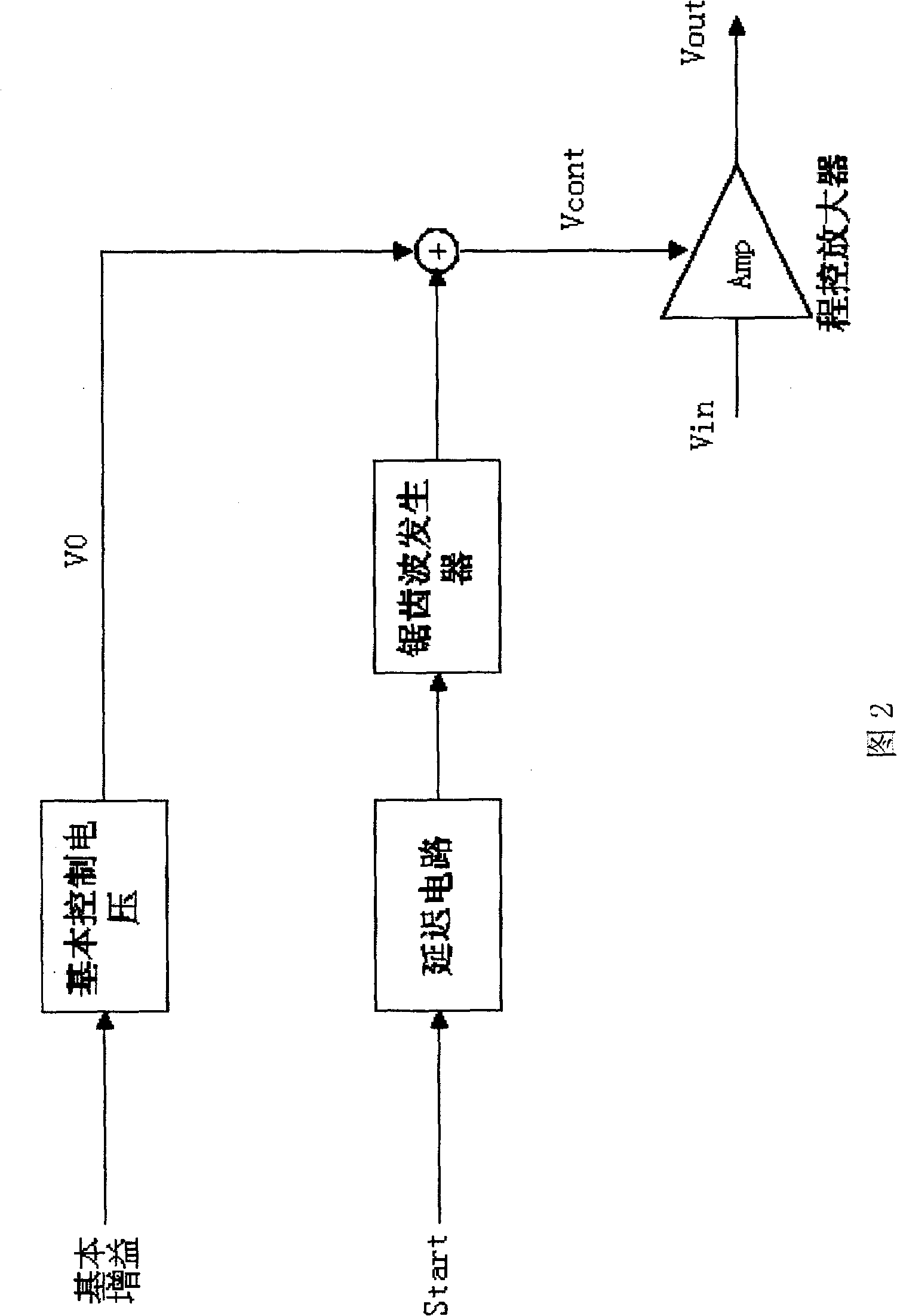
[0034] Such as Figure 3-5 As shown, the gain compensation method of the flaw detector in this preferred embodiment, the method controls the voltage of the voltage control terminal of the program-controlled amplifier voltage of the flaw detector through a device including a CPU module, a programmable logic device and a digital-to-analog converter, and realizes gain compensation , the method includes the following steps:

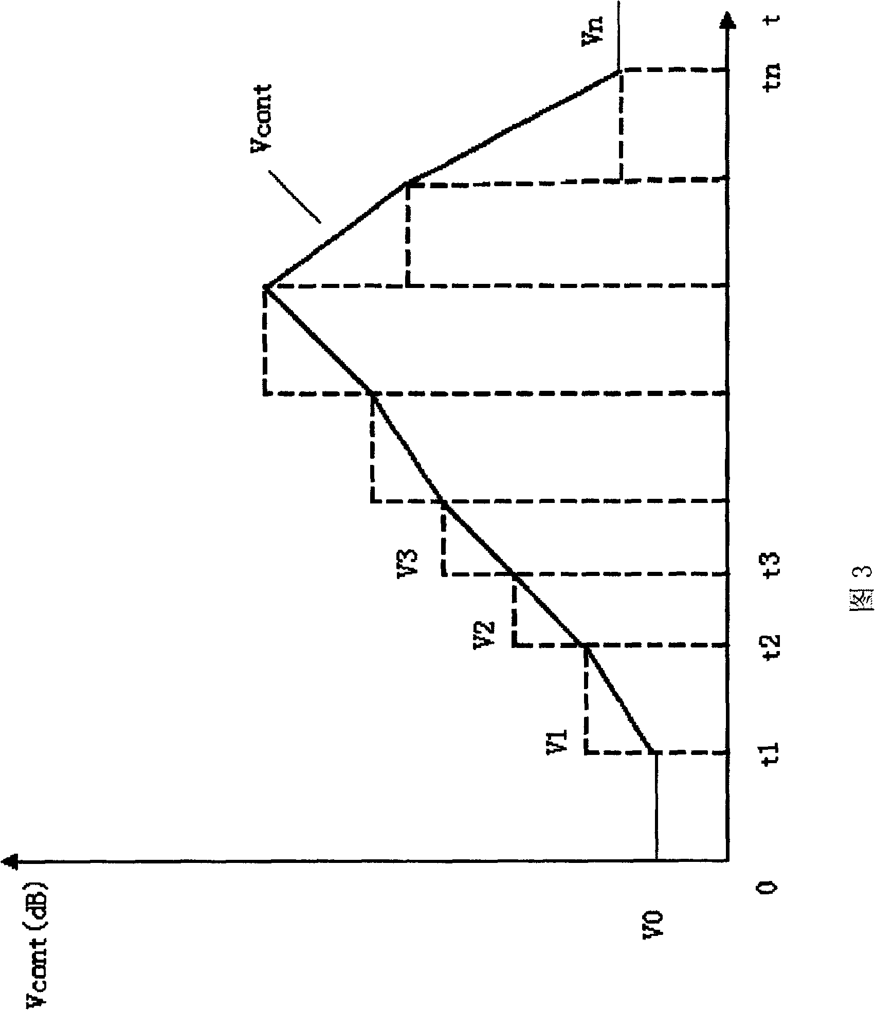
[0035] (1) Set all time parameters of each channel (the time parameter is the count value of a certain time) and the gain data parameters corresponding to each time parameter;

[0036] (2) The control panel transmits the channel number signal to the CPU module;

[0037] (3) The CPU module transmits the parameters of the corresponding channel to the programmable logic device according to the channel number, and starts the programmable logic device at the same time;

[0038] (4) the programmable logic device timing, and the time value of the timing (the count...


PUM


Abstract

A method for gain compensation of a flaw detector, the method controls the voltage of the voltage control terminal of the program-controlled amplifier voltage of the flaw detector through a device containing a CPU module, a programmable logic device and a digital-to-analog converter to realize gain compensation, and the method includes the following steps: (1) Set the time parameters of each channel and the corresponding gain data parameters; (2) The control panel transmits the channel number signal to the CPU module; (3) The CPU module transmits the corresponding channel parameters to the control panel according to the channel number. Program the logic device and start the programmable logic device at the same time; (4) the programmable logic device clocks, and compares the time value of the clock with each time parameter of the channel parameter; (5) if the time value of the clock is equal to a certain value in the channel parameter time parameter, then output the gain data corresponding to the time parameter in the channel parameter to the digital-to-analog converter; (6) the digital-to-analog converter converts the gain data into a control voltage, transmits it to the program-controlled amplifier, and returns to step 4.

Description

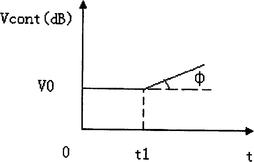
technical field [0001] The invention relates to a gain compensation method of a flaw detector. Background technique [0002] In the application of ultrasonic flaw detection, after the ultrasonic wave is emitted by the transducer, the sound wave gradually attenuates when it propagates in the workpiece to be tested. Therefore, if there is a defect in the workpiece to be tested, the sound intensity of the sound wave reflection decreases with the increase of the depth of the defect. In order to make deep defects more obvious, in some applications, the gain of the ultrasonic receiving amplifier is usually designed to increase with the increase of depth (ie time), that is, depth compensation. Amplifiers that can achieve deep compensation are also called program-controlled amplifiers, namely Amp. Most of them have been made into integrated circuits. Its amplification varies with the voltage of the voltage control terminal, and its gain (dB) is almost linear with the control voltage...

Claims


Application Information

Patent Timeline
Patent Type & Authority Patents(China)
IPC IPC(8): G01N29/44
Inventor 刘悟日林广峰卢可金张定成陈泽斌
Owner GUANGDONG GOWORLD
Why Eureka
Try Eureka