Calorimeter having barrelhead with flow guiding circulating temperature controlling device

A technology of temperature control device and diversion cycle, which is applied in the field of calorimeters, can solve the problems of reduced accuracy of test results, uncertain degree of intensity, poor reproducibility, etc., and achieve shortened test time, strong reproducibility, and improved adaptability The effect of harsh environment capability

Active Publication Date: 2009-09-23
HUNAN SUNDY SCI & TECH DEV
View PDF7 Cites 0 Cited by
  • Summary
  • Abstract
  • Description
  • Claims
  • Application Information

AI Technical Summary

Problems solved by technology

Due to the different nature of endothermic and exothermic, and the degree of intensity is uncertain each time, the process is long. During this process, the temperature of the outer barrel changes very complicatedly, and the heat capacity of the instrument may also change, resulting in a decrease in the accuracy of the test results and a reproducibility. Sexual deterioration

Method used


Image

  • Calorimeter having barrelhead with flow guiding circulating temperature controlling device
  • Calorimeter having barrelhead with flow guiding circulating temperature controlling device
  • Calorimeter having barrelhead with flow guiding circulating temperature controlling device

Examples


Embodiment 1

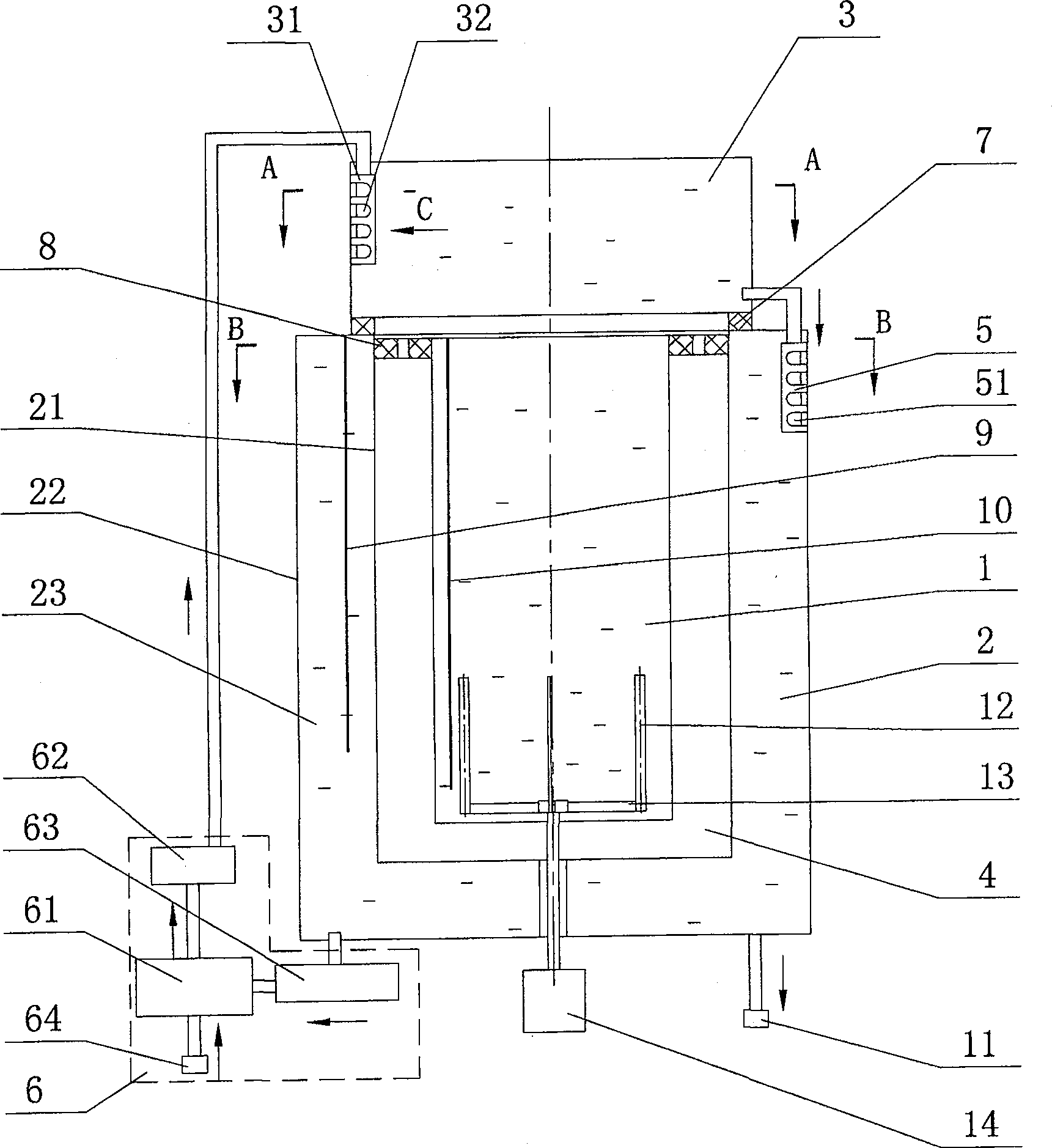
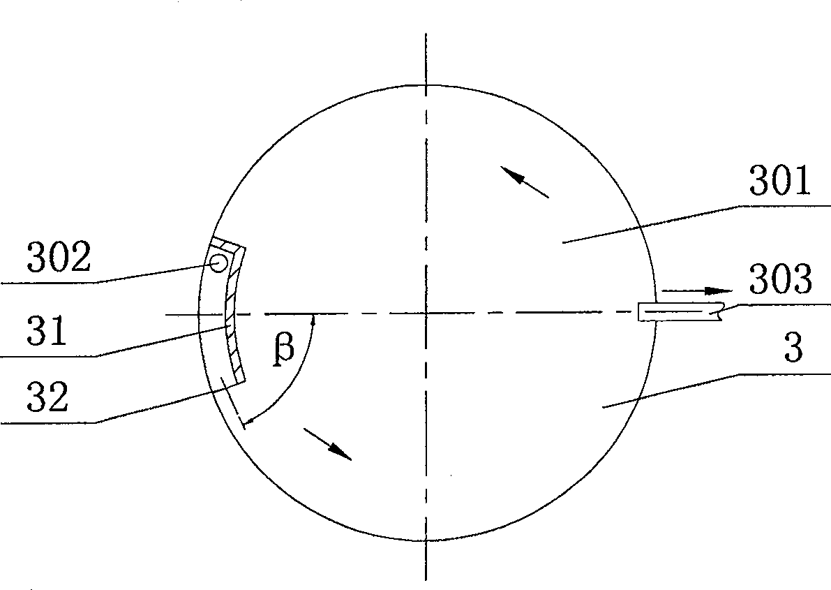
[0056] Embodiment 1: as figure 1 , figure 2 and Figure 4 As shown, one or more cover guide chambers 31 are provided in the bung 3, and several cover guide chamber openings 32 are provided on the cover guide chamber 31; the entrance of the cover guide chamber 31 and the cover medium inlet 302 The mouth of the cover guide cavity 32 is in communication with the entrance of the cover guide cavity 31 . The medium can be sprayed into the cover cavity 301 from the cover diversion cavity 32, and the medium in the cover cavity 301 is continuously pushed forward by the injection medium, thereby forming the self-flow agitation of the medium, and reaching the temperature trend of each place in the cover cavity 301. to a consistent effect. Wherein the lid diversion cavity 32 can adopt circular hole shape, slit shape or other irregular shapes according to the concrete needs of spraying, also can be by changing the α1 angle that lid diversion cavity 32 and bung 3 upper planes form in ad...

Embodiment 2

[0057] Embodiment 2: as Figure 6 , Figure 7 , Figure 9 , Figure 10 and Figure 12 As shown, one or more cover deflectors 33 are provided in the barrel cover 3, and the cover guide body 33 is centered on the center of the barrel cover 3, and is spirally distributed in the cover cavity 301 in the shape of an equal or non-equal diameter arc. Inside, and form a non-closed lid diversion groove 34 with the side wall of the barrel lid 3; the starting point of the lid diversion body 33 is located below the lid medium inlet 302. The medium enters the cover cavity 301 from the cover medium inlet 302. Under the diversion restriction of the cover guide body 33, part of the medium will flow along the cover guide groove 34, and then drive other media to flow in a certain direction, forming the self-flow of the medium Stir to achieve the effect that the temperature in the lid cavity 301 tends to be consistent everywhere. Among them, the cover diversion body 33 can change the α2 angl...


PUM


Abstract

The invention discloses a calorimeter with a diversion cycle temperature control device on the barrel cover, which comprises an inner barrel, an outer barrel and a barrel cover arranged on the top of the inner barrel and the outer barrel, the inner barrel is placed in the outer barrel, and the outer wall of the outer barrel is An outer barrel cavity filled with medium is formed between the inner barrel and the outer barrel, an air interlayer is provided between the inner barrel and the outer barrel, and one or more cover diversion chambers or one or more The cover diversion body, the cover diversion cavity or the cover diversion body and the circulation supply device form a diversion circulation temperature control device, and the circulation supply device includes a temperature control device and a driving device. The invention is a calorimeter with a diversion cycle temperature control device on the lid that can keep the temperature inside the barrel lid and the outer barrel constant and create an ideal external environment for the inner barrel, thereby improving the ability of the instrument to adapt to harsh environments and improving test accuracy.

Description

technical field [0001] The invention mainly relates to a measuring instrument for measuring the calorific value of coal, oil or other heating substances in coal, petrochemical or electric power industries, in particular to a calorimeter with a diversion cycle temperature control device on the barrel cover. Background technique [0002] In the prior art, the measuring instruments used to determine the calorific value of substances are generally composed of an inner barrel, an outer barrel and a barrel cover arranged on the top of the inner barrel, wherein the inner barrel is arranged in the outer barrel; when testing, the oxygen bomb of the test sample is placed on the In the inner barrel, it is connected with the ignition electrode, and the ignition is energized at the specified time, so that the sample can be fully burned. In order to ensure accurate determination of the calorific value of the substance, the temperature of the outer barrel must be kept constant. When the am...

Claims


Application Information

Patent Timeline
Patent Type & Authority Patents(China)
IPC IPC(8): G01K17/06
Inventor 朱先德
Owner HUNAN SUNDY SCI & TECH DEV
Why Eureka
Try Eureka