Check patentability & draft patents in minutes with Patsnap Eureka AI!

Method of operating an internal combustion engine

A technology of internal combustion engine and operating mode, applied in the direction of internal combustion piston engine, combustion engine, mechanical equipment, etc., can solve the problems of increasing cost and complexity, difficulty in installing the limited space of engine combustion chamber, etc., and achieve the effect of cost saving

Inactive Publication Date: 2009-09-30
BRUNEL UNIVERSITY
View PDF6 Cites 0 Cited by
  • Summary
  • Abstract
  • Description
  • Claims
  • Application Information

AI Technical Summary

Problems solved by technology

However, such systems add cost and complexity, and are difficult to fit in the confined space of an engine's combustion chamber

Method used


Image

  • Method of operating an internal combustion engine
  • Method of operating an internal combustion engine
  • Method of operating an internal combustion engine

Examples


Embodiment Construction

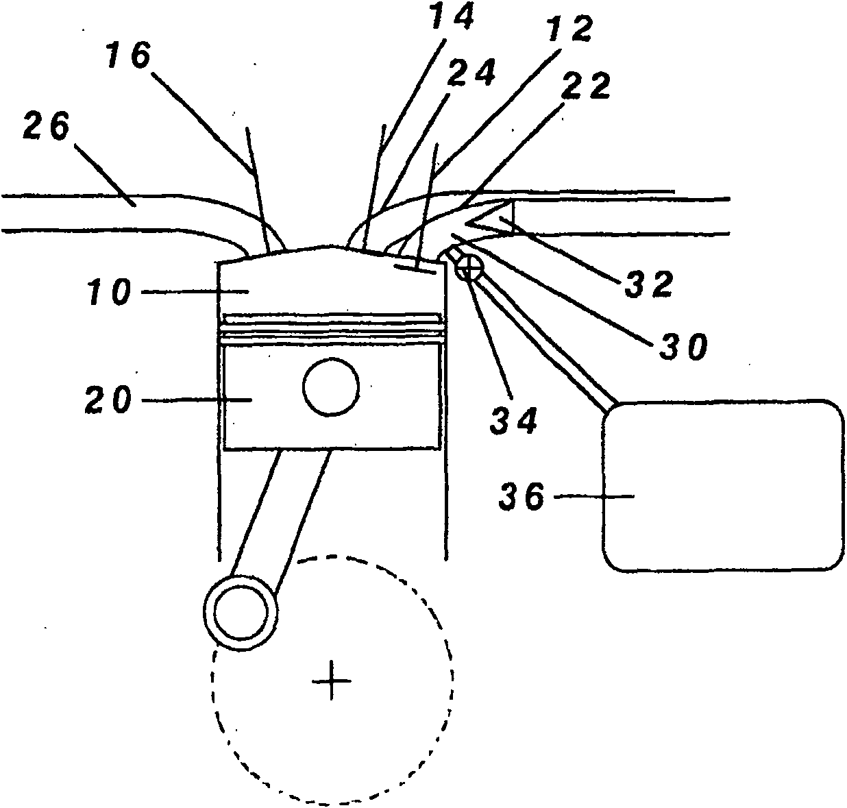
[0025] figure 1 An internal combustion engine is shown having first and second intake ports 24, 22 in each cylinder working together with an exhaust port 26, where each port is controlled by an associated valve 14, 12, 16 , these valves are timed to open and close during the intake or exhaust phases of the engine cycle to control the intake and exhaust of the engine. In the second air inlet 22 there is additionally a one-way reed valve 32 positioned in such a way that when the air inlet 22 and the one-way valve 32 are controlled by the arm from the local area where the delivery pressure from the ambient air is high Pressure, the valve 32 automatically closes in a direction away from the engine cylinder 10 . The engine also includes a fuel system and an ignition system, not shown.

[0026] In the above engine, a variable valve actuation system (not shown) is provided for the intake valves 12 , 14 . This is completely flexible and variable as in an electronically controlled c...


PUM


Abstract

An internal gas transfer method for operating an engine with at least a first and a second intake port controlled by respective first and second poppet valves normally timed to open and close during the intake period of the engine cycle. Variable valve timing is provided for at least the second poppet valve, and a non-return valve is mounted in the second intake port positioned such that the valve automatically shuts in the flow direction away from the engine cylinder when the said port and the non-return valve are subjected to a pressure higher than the intake air supply pressure. An auxiliary chamber is provided which communicates with the cylinder via the second intake port and downstream of the non-return valve. When internal gas transfer is required, the second poppet valve is moved in timing to open and close during a period other than the air intake period of the engine cycle, thus briefly connecting the second intake port and non-return valve with the engine cylinder, shutting the said non-return valve, and permitting transfer of gas between the cylinder and the auxiliary chamber during the power conversion phase of the engine cycle.

Description

technical field [0001] The invention relates to a method of operating an internal combustion engine. Background technique [0002] It is known, in order to influence the compression or expansion process, to provide a secondary combustion chamber which is connected or disconnected from the engine cylinders during the compression or expansion periods of the engine cycle. EP0095252 proposes to use such a secondary chamber to trap a fraction of the cylinder charge during compression, which fraction is variable, in order to vary the effective compression ratio of the engine. Pending patent application PCT / GB2004 / 001018 proposes to use the secondary combustion chamber as a buffer chamber in an air hybrid engine vehicle to send compressed gas in two steps through the This secondary combustion chamber delivers to the compressed gas storage and expands the compressed gas from the compressed gas storage via the secondary combustion chamber in two steps when the engine is operated as ...

Claims


Application Information

Patent Timeline
Patent Type & Authority Patents(China)
IPC IPC(8): F01L13/08F02D13/02F02D15/00F02D21/08F02M23/00F02M25/07F02M35/10F02M35/108
CPCY02T10/146F02M35/1042F02M35/10295Y02T10/18F02M35/10275F02D13/0257F02M23/005F02B29/00F02D15/00F02B21/00F02M35/1085F02D13/0238Y02T10/12
Inventor 托马斯·T·马
Owner BRUNEL UNIVERSITY
Features
  • R&D
  • Intellectual Property
  • Life Sciences
  • Materials
  • Tech Scout
  • Unparalleled Data Quality
  • Higher Quality Content
  • 60% Fewer Hallucinations
Learn More