
Permanent magnet type rotary electric machine and compressor using it

A rotating electrical machine, permanent magnet technology, applied in rotating piston machines, synchronous motors with stationary armatures and rotating magnets, rotating piston/swing piston pump components, etc., can solve the problem of reducing pulsating torque, etc. question

Inactive Publication Date: 2009-09-30
HITACHI IND EQUIP SYST CO LTD
View PDF8 Cites 0 Cited by
  • Summary
  • Abstract
  • Description
  • Claims
  • Application Information

AI Technical Summary

Problems solved by technology

In order to reduce these problems, although it is possible to implement inclination on the rotor or stator core, even if only the cogging torque is reduced, there is a problem that the actual pulsating torque cannot be greatly reduced

Method used


Image

  • Permanent magnet type rotary electric machine and compressor using it
  • Permanent magnet type rotary electric machine and compressor using it
  • Permanent magnet type rotary electric machine and compressor using it

Examples


Embodiment 1

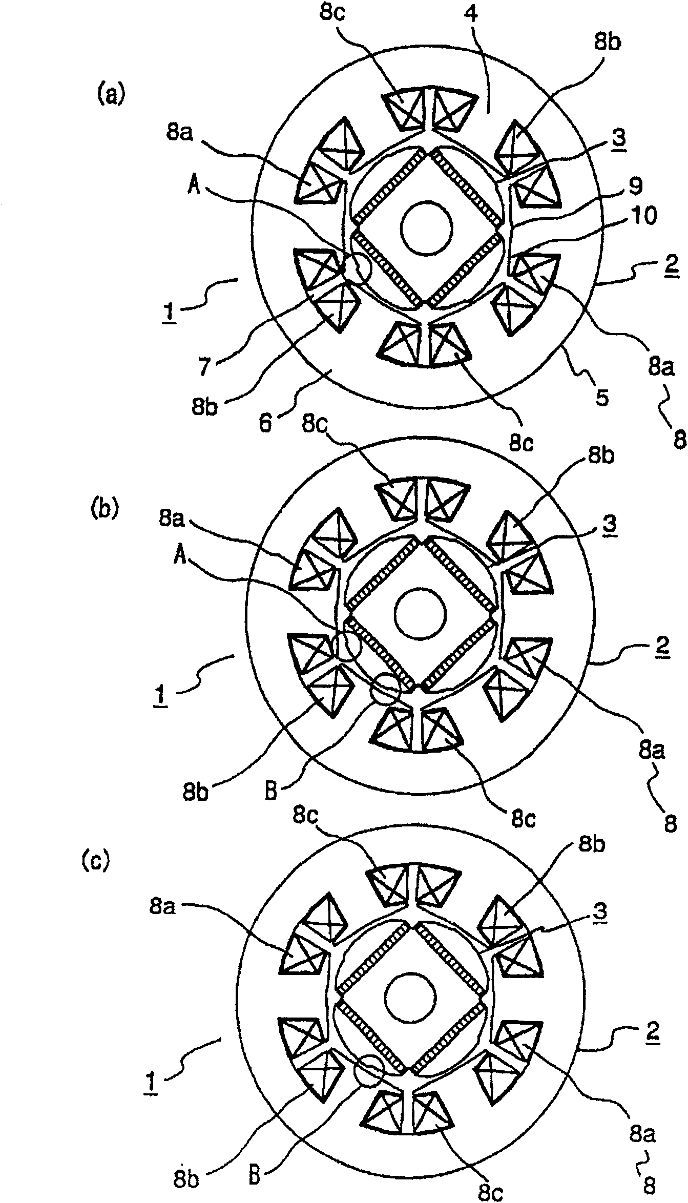
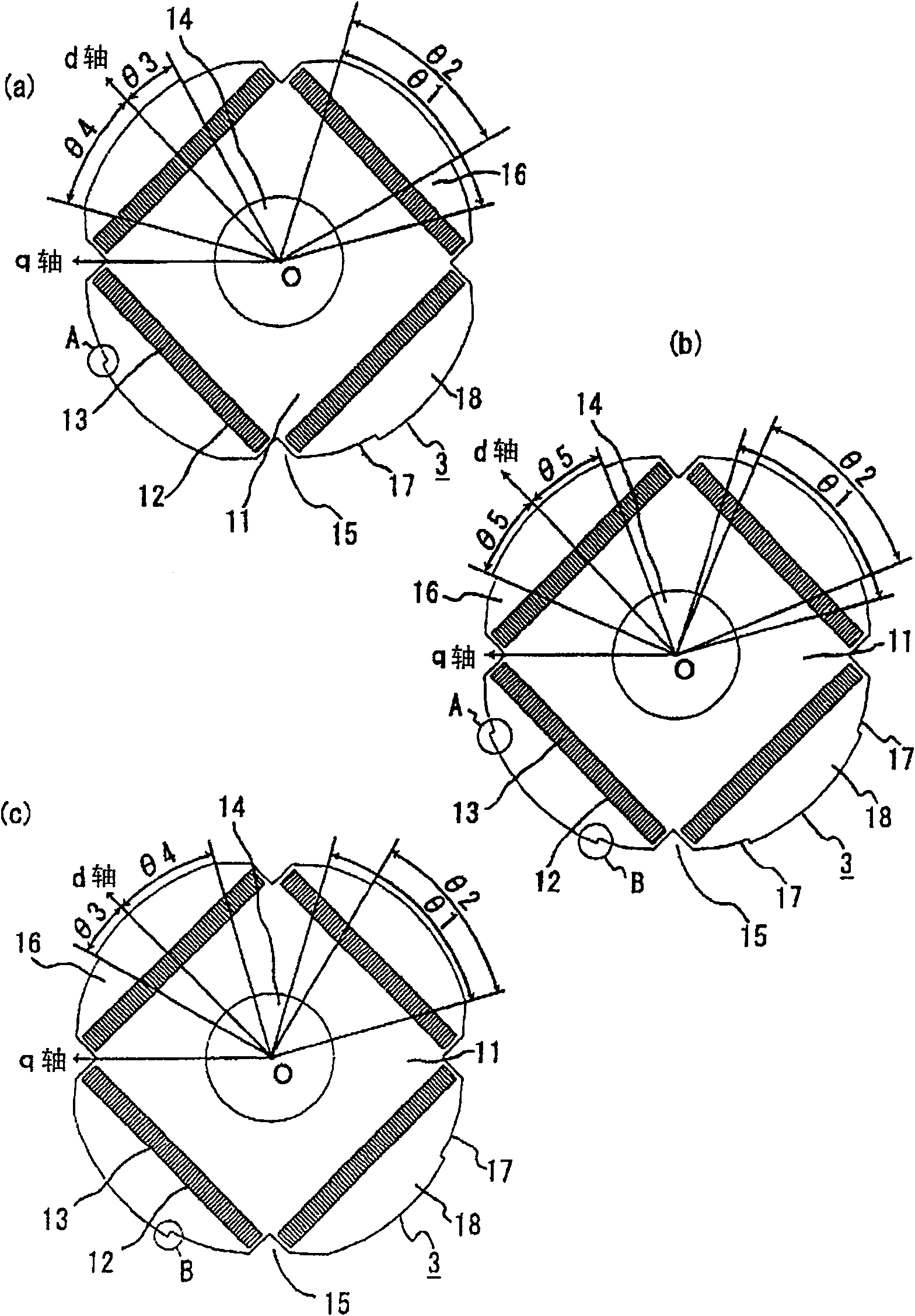
[0065] The axial cross section of the stator 2 in the first embodiment is the same at any position, but the axial cross section of the rotor 3 differs depending on the position. Figure 4 A perspective view of a rotor according to Embodiment 1 of the present invention is shown. exist Figure 4 Among them, the inline permanent magnets 13 are accommodated in the permanent magnet insertion holes 12 which are continuous at the same position along the axial direction, and only the circumferential position of the magnetic pole portion 18 is different according to the axial direction. In other words, the positions of the pole cores of the rotor are shifted in a stepwise manner with respect to the axial direction.

[0066] However, in the permanent magnet type rotating electrical machine 1 for driving a compressor which is the object of the present invention, there is always a problem of noise generation. The ripple torque is a main factor that increases the noise of the permanent m...


PUM


Abstract

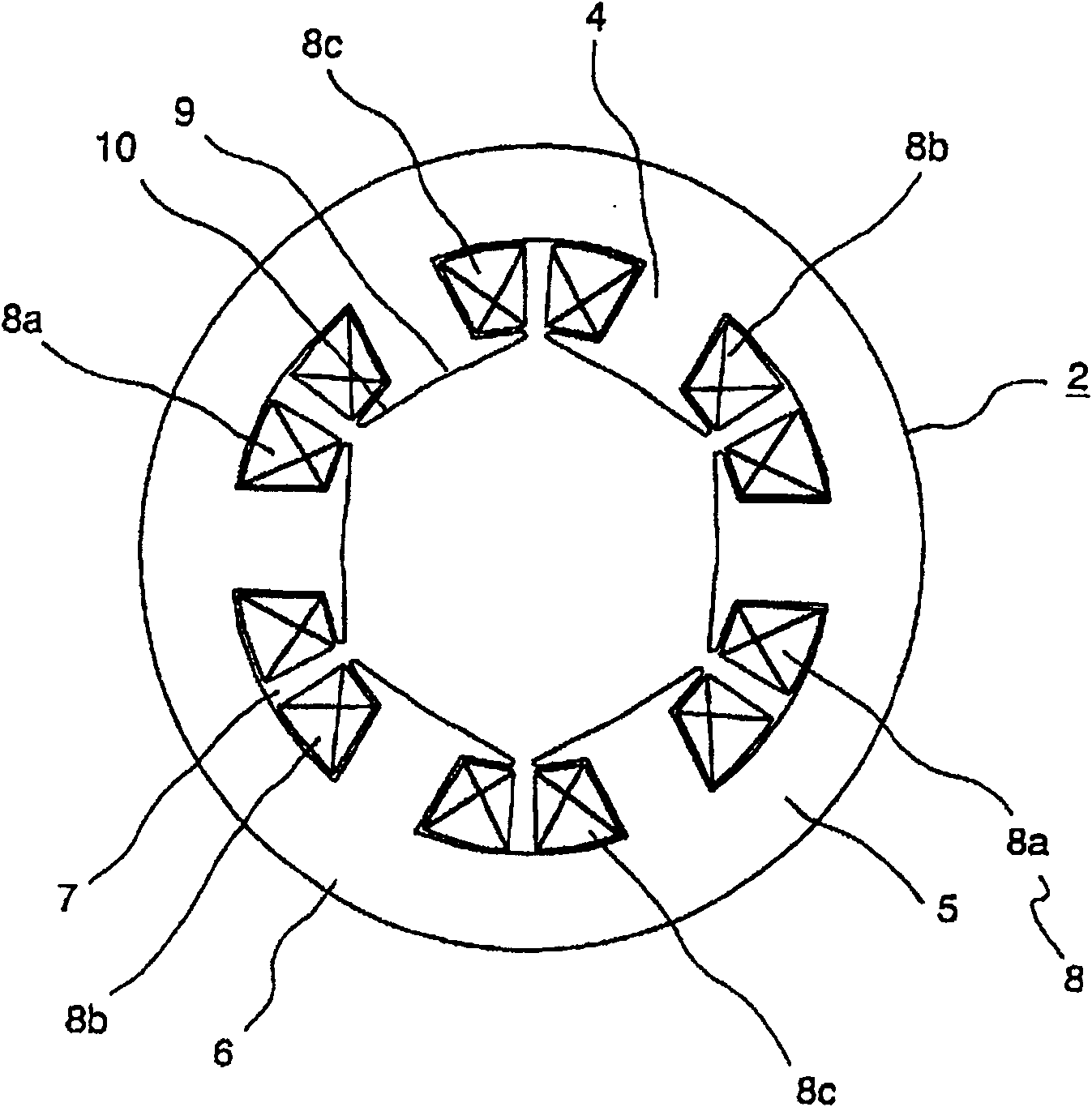
A permanent-magnet rotating electrical machine and a compressor using the same. In the permanent-magnet rotating electrical machine, when the magnetic flux axis of the permanent magnet is taken as the d-axis and the axis perpendicular to it is taken as the q-axis, the rotor iron The permanent magnet insertion hole on the core is arranged at the same position in the axial direction, and the magnetic pole core is formed so that the gap length on the q-axis side is longer than the gap length on the d-axis side in order to converge the magnetic flux of the permanent magnet. A plurality of clearance surfaces are provided on the outer peripheral surface of the core, and the position of the magnetic pole core is arranged in a stepwise staggered manner relative to the axial direction, so that the phase difference between the ripple torque and the cogging torque based on the winding is 180 degrees. Since the ripple torque during operation is halved, noise reduction can be achieved.

Description

[0001] This application is a divisional application, the application number of its parent application is: 03147457.8, the application date: 2003.7.11, the name of the invention: permanent magnet rotary motor and compressor using the motor technical field [0002] The present invention relates to a permanent magnet rotating electrical machine having a rotor with permanent magnets for forming a magnetic field, and more particularly to a permanent magnet rotating electrical machine mounted in compressors such as air conditioners, refrigerators, and freezers. Background technique [0003] Conventionally, various shapes have been employed in such permanent magnet rotating electric machines. For example, in the permanent magnet type rotating electrical machine described in Japanese Patent Laid-Open No. 2000-175389, by setting the shape of the outer peripheral surface after one side of the magnetic pole of the rotor core is cut and then inverting it in the axial direction to laminat...

Claims


Application Information

Patent Timeline
Patent Type & Authority Patents(China)
IPC IPC(8): H02K1/27F04B39/00F04C18/02F04C29/00H02K1/06H02K1/14H02K19/10H02K21/24
Inventor 湧井真一小原木春雄菊地聪妹尾正治野间启二
Owner HITACHI IND EQUIP SYST CO LTD
Learn More