Supercharge Your Innovation With Domain-Expert AI Agents!

Method for manufacturing driveway module, and driveway module

A technology of rails and trains, applied in the field of steel driving rail modules

Inactive Publication Date: 2009-10-07
THYSSENKRUPP TRANSRAPID
View PDF12 Cites 0 Cited by
  • Summary
  • Abstract
  • Description
  • Claims
  • Application Information

AI Technical Summary

Problems solved by technology

[0013] Despite the stated prior art, the hitherto known running rails, running rail modules and methods for their production are not satisfactory everywhere

Method used


Image

  • Method for manufacturing driveway module, and driveway module
  • Method for manufacturing driveway module, and driveway module
  • Method for manufacturing driveway module, and driveway module

Examples


Embodiment Construction

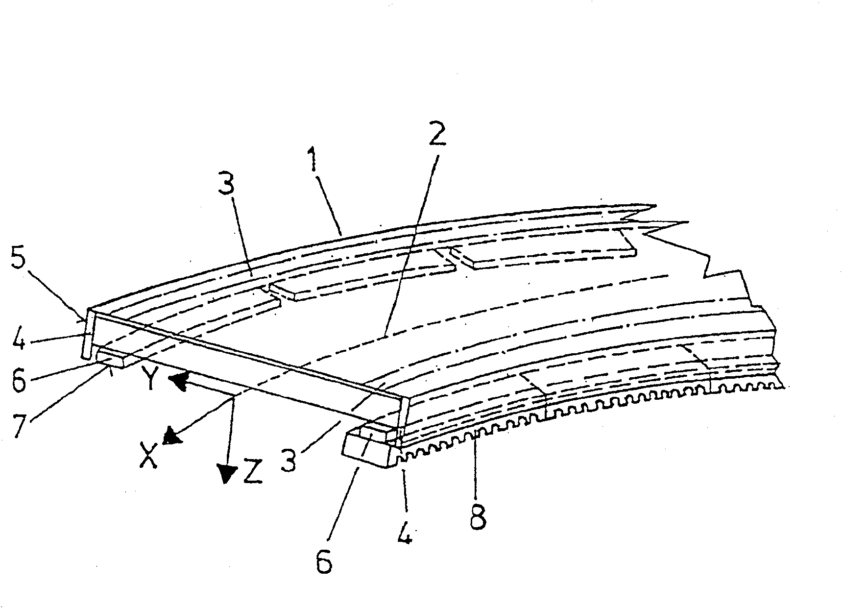
[0035] figure 1 An idealized representation of a steel track module 1 is shown, which is suitable for building the track of a maglev railway with a long stator linear field motor. This exemplary embodiment is a module 1 which is curved completely along a predetermined railway line, as indicated by a spatial curve 2 which is shown in the plane. Furthermore, a rectangular coordinate system with mutually perpendicular axes x, y and z is shown schematically. where curvature around the x-axis means a lateral inclination in the sense of a curve superelevation, curvature around the y-axis means a section of roadway passing through a rounded crest or a valley and curvature around the z-axis means a curve drive.

[0036] The module 1 has on its upper side two parallel, substantially horizontally arranged and serves as part of the sliding surface 3 and on its longitudinal sides two substantially vertical side rails 4 which are provided with side guide surfaces 5 on their outer sides ...


PUM


Abstract

The invention relates to a running rail module (10) used for the running rail of a maglev train. The module (10) has functional surfaces (17, 18, 19) in the form of at least one each of a side guide surface, a sliding surface and a mounting surface of the stator laminations. According to the invention the functional surfaces (17, 18, 19) are formed on fittings (14, 15) which are fixedly connected to the module (10), have allowances and are made of steel and are cut to preselected nominal dimensions by machining. , 16) On. Furthermore, it relates to a running track composed of such modules and a method for producing the modules (10), which comprises elastically twisting the modules after they have been fastened to the girder, in order thereby to produce a change in transverse inclination.

Description

technical field [0001] The invention relates to a method for manufacturing a steel rail module for a magnetic levitation train and a steel rail module for a magnetic levitation train. Background technique [0002] Two types of running rails with functional surfaces are required for the drive and track guidance of maglev trains with long stator linear field motors. At least one first functional surface in the form of a side guide surface, which is fastened to a first fitting in the form of a side guide rail, serves as a track guide. At least a first functional surface in the form of a further sliding surface is required during normal or emergency parking of the maglev train and is formed on the first fitting in the form of a further sliding strip. Finally, the functional surface in the form of a second mounting surface is used for subsequent mounting of the stator laminations of the long-stator linear field machine and is formed on the fitting in the form of a second stator ...

Claims


Application Information

Patent Timeline
Patent Type & Authority Patents(China)
IPC IPC(8): E01B25/30E01B25/32
CPCE01B25/32E01B25/305
Inventor 约翰·马图舍克托马斯·施蒂尔弗朗茨-克萨韦尔·皮希尔迈尔卡尔·费施特纳卡尔·基尔施泰因沃尔夫冈·基尔施泰因
Owner THYSSENKRUPP TRANSRAPID
Features
  • R&D
  • Intellectual Property
  • Life Sciences
  • Materials
  • Tech Scout
  • Unparalleled Data Quality
  • Higher Quality Content
  • 60% Fewer Hallucinations
Learn More