Optical fibre electric current sensor sensitive coil winding equipment

A technology of sensitive coil and fiber optic current, applied in voltage/current isolation, measurement of current/voltage, instruments, etc., can solve problems such as uncomfortable and accurate control, complex structure, easy to introduce torsional stress, etc., to avoid torsional stress and ensure consistency , the effect of simple operation

Active Publication Date: 2009-10-14
BEIJING AEROSPACE TIMES OPTICAL ELECTRONICS TECH
View PDF3 Cites 0 Cited by
  • Summary
  • Abstract
  • Description
  • Claims
  • Application Information

AI Technical Summary

Problems solved by technology

Because it is designed for winding fiber optic gyroscopes over 100 meters long, it needs electric control and complex structure. The fiber to be wound needs to be wound on the driven wheel in advance. The distance between the fiber optics between the driving wheel and the driven wheel is relatively large, and the fibers are closely arranged It is impossible to accurately control the fiber spacing and fiber tensile stress, and it is easy to introduce torsional stress, so it is not suitable for accurate control of fiber spacing and stress. The winding process requires manual monitoring, and the fiber is only a few meters. The sensitive coil of the fiber optic current sensor

Method used


Image

  • Optical fibre electric current sensor sensitive coil winding equipment
  • Optical fibre electric current sensor sensitive coil winding equipment

Examples


Embodiment Construction

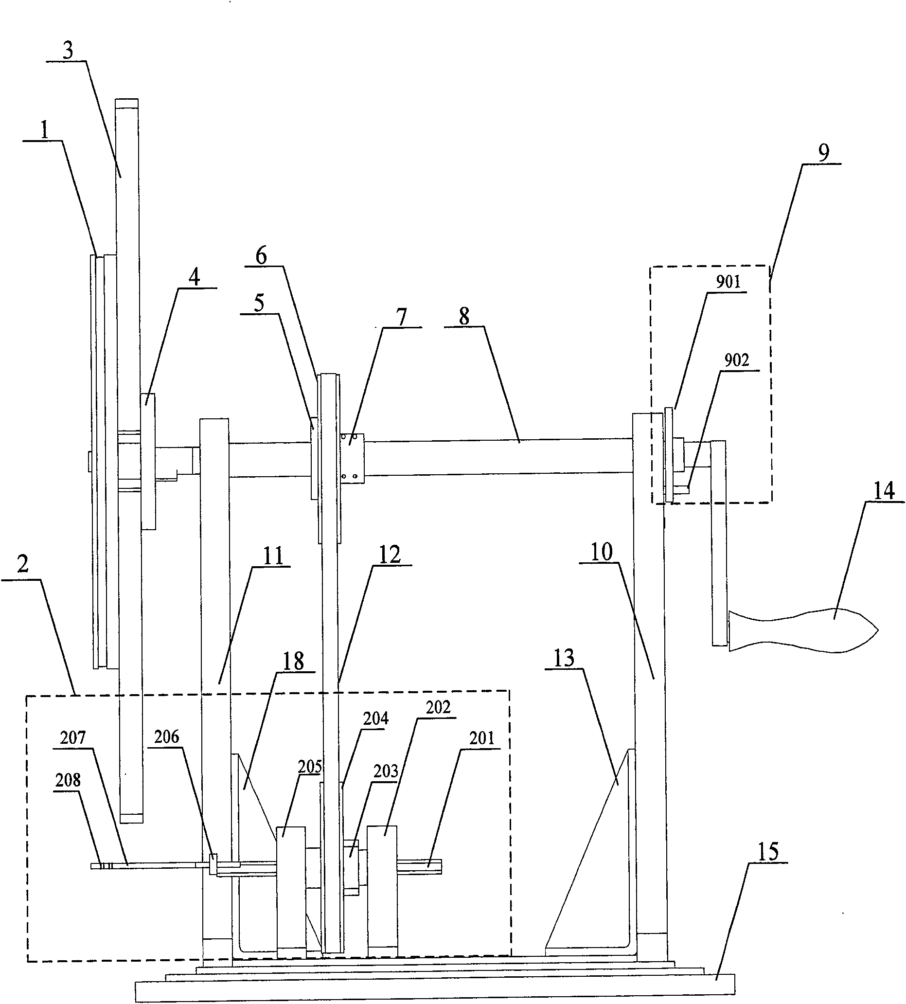
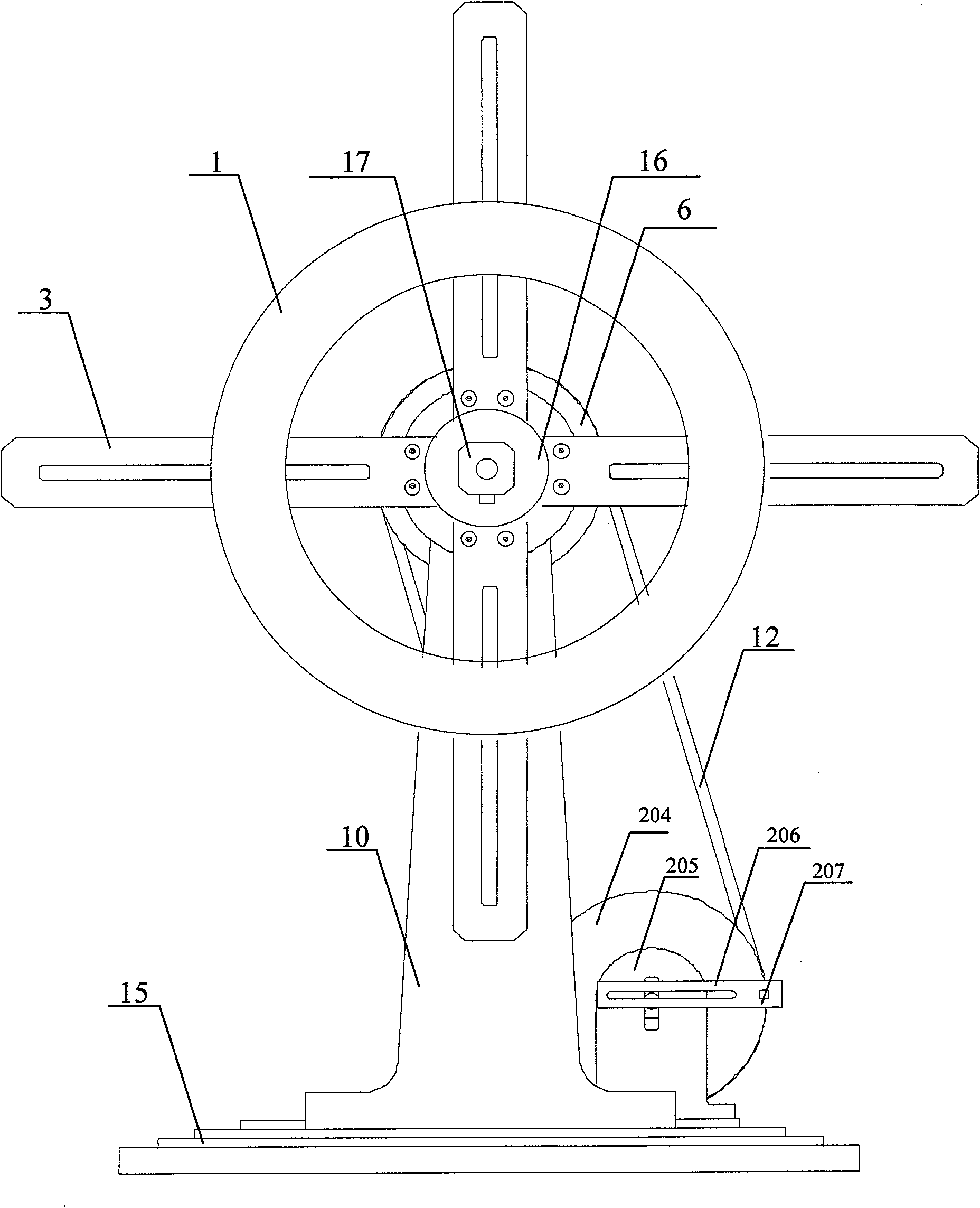
[0016] Such as figure 1 and 2 As shown, the optical fiber current sensor sensitive coil winding equipment of the present invention includes a fiber guide mechanism 2, a skeleton mounting seat 3, a shaft coupling 4, 5, 7, a driving wheel 6, a main shaft 8, a locking mechanism 9, a main shaft bearing seat 10, 11. Transmission belt 12, supporting bone 13, 18, handle 14, base 15, pressure plate 16, nut 17; on the main shaft 8, there are nut 17, pressure plate 16, skeleton mounting seat 3, driving wheel 6, lock in turn from left to right The tightening mechanism 9 and the handle 14, the nut 17 and the pressure plate 16 fix the sensitive coil skeleton 1 on the skeleton mounting seat 3, the skeleton mounting seat 3 and the driving wheel 6 are installed on the main shaft 8 through the couplings 4, 5, 7, and the main shaft The bearing housings 10, 11 are fixed on the base 15 through the supporting bones 13, 18 and are respectively located on both sides of the driving wheel 6 to fix th...


PUM


Abstract

Sensitive coil winding equipment of an optical fiber current sensor comprises a nut, a pressure plate, a frame arrangement base, a drive wheel, a lock mechanism and a handle, which are sequentially arranged on a spindle from left to right, wherein a sensitive coil frame is fixed on the frame arrangement base by the nut and the pressure plate; the frame arrangement base and the drive wheel are arranged on the spindle through a coupling; a spindle bearing base is fixed on a pedestal through a support frame and are respectively positioned on both sides of the drive wheel to fix the spindle; the spindle and the coil frame can be driven to rotate by shaking the handle and further to drive the drive wheel to rotate and drive a fiber guide mechanism to operate through a transmission belt; and the lock mechanism is arranged between the handle and the spindle bearing base close to the handle for locking the rotation of the spindle, so that the coil frame is kept as the original position. The winding equipment has the advantages of no external torsion stress to optical fiber, controllable fiber tension, adjusting fiber pitch, simple operation, etc., and can be used for winding sensitive coil of interferometric optical fiber current sensor to ensure the performance uniformity of the sensitive coil.

Description

technical field [0001] The invention relates to a winding device for a sensitive coil of an optical fiber current sensor. Background technique [0002] The optical current sensor (OCT) sensitive coil made of single-mode fiber or low birefringence fiber will respond to the magnetic field change caused by the current flowing through the conductor due to the magneto-optic Faraday effect when the polarized light is transmitted inside. , resulting in a phase shift. Since the optical fiber sensitive coil is installed on the high-voltage line, affected by the external environment temperature, the response of the optical fiber current sensor (OCT) will change with the change of temperature, resulting in errors in the test results. Under the environment (-40 ~ +65 ℃), it is difficult to achieve high-precision measurement with an error of less than 0.2%. [0003] The main causes of OCT temperature sensitivity are internal residual stress and uneven core diameter of the fiber core, o...

Claims


Application Information

Patent Timeline
Patent Type & Authority Patents(China)
IPC IPC(8): G01R15/18G01R19/00
Inventor 张志鑫谭金权王学锋冯振华
Owner BEIJING AEROSPACE TIMES OPTICAL ELECTRONICS TECH
Why Eureka
Try Eureka