Pressure medium spring and transmission nut using same

A pressure medium and pressure technology, applied in the direction of transmission, transmission parts, belts/chains/gears, etc., can solve the problems of unfavorable transmission accuracy of ball screw pairs, high maintenance costs, wear and tear of the use section, and achieve the elimination of reverse Transmission clearance, long service life and less wear

Pending Publication Date: 2021-11-12
田间 +1
View PDF0 Cites 0 Cited by
  • Summary
  • Abstract
  • Description
  • Claims
  • Application Information

AI Technical Summary

Problems solved by technology

However, there is a fatal shortcoming in the double-nut structure currently used. In order to meet the axial bearing capacity of the machine tool, the double-nut screw pair is realized by increasing the pre-tightening force between the double-nuts. Excessive pre-tightening The force accelerates the wear of the lead screw
And because only a certain section of the screw stroke is often used, after a period of use of the new screw product, the use section is severely worn, and the backlash of the ball screw in this section of the stroke that cannot be guaranteed to be used uniformly throughout the stroke must It will be larger than the backlash of the infrequently used section; at this time, neither the mechanical method nor the electrical method can fully compensate the different backlash on the same screw, so it will inevitably affect the ball. The transmission accuracy of the screw pair causes certain disadvantages and the impact that cannot be eliminated at present
Once the above-mentioned excessive "uneven wear" phenomenon occurs in a certain stroke of the screw, it is necessary to disassemble the transmission part of the entire machine tool, take out the screw, and replace it as a whole, which brings high maintenance costs

Method used


Image

  • Pressure medium spring and transmission nut using same
  • Pressure medium spring and transmission nut using same
  • Pressure medium spring and transmission nut using same

Examples


Embodiment Construction

[0036] Embodiments of the present invention will be described in more detail below with reference to the accompanying drawings. Although certain embodiments of the invention are shown in the drawings, it should be understood that the invention may be embodied in various forms and should not be construed as limited to the embodiments set forth herein; A more thorough and complete understanding of the present invention. It should be understood that the drawings and embodiments of the present invention are for exemplary purposes only, and are not intended to limit the protection scope of the present invention.

[0037] It should be noted that concepts such as "first" and "second" mentioned in the present invention are only used to distinguish different devices, modules or units, and are not used to limit the sequence of functions performed by these devices, modules or units or interdependence.

[0038]It should be noted that the modifications of "one" and "multiple" mentioned i...


PUM


Abstract

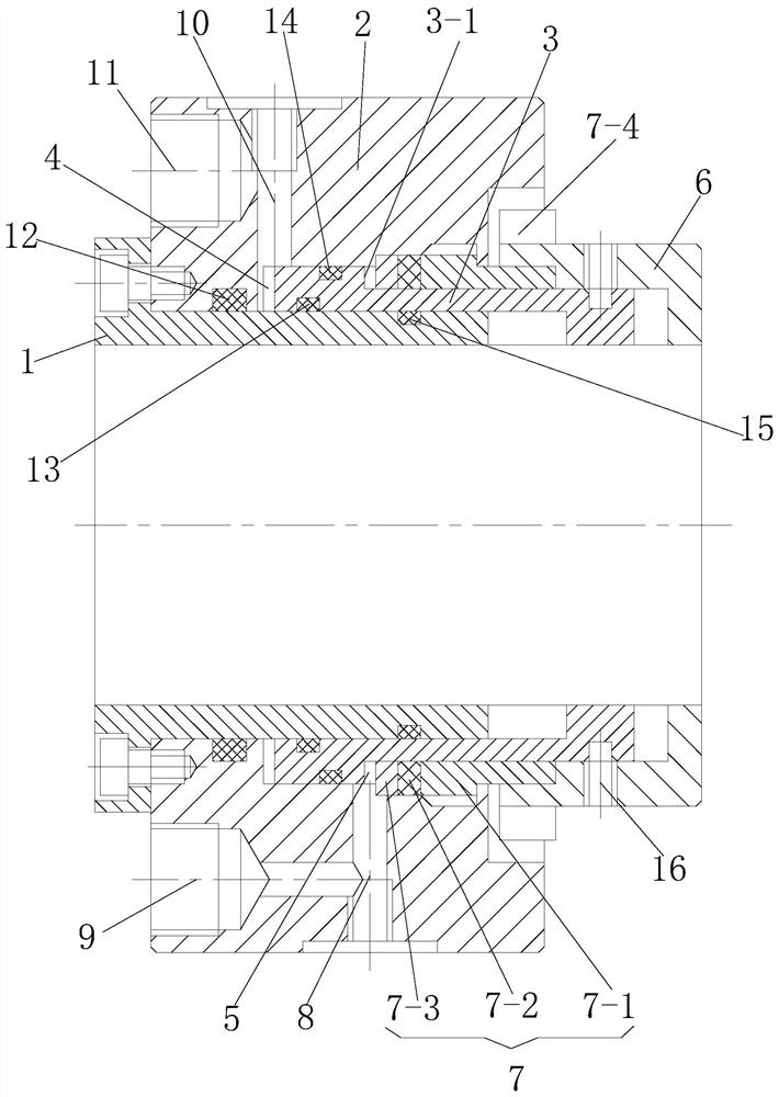
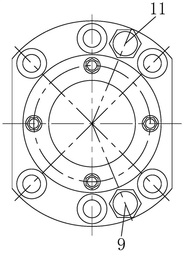
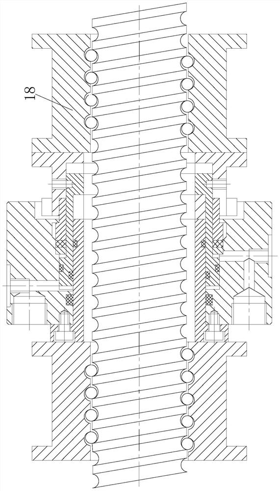
The invention discloses a pressure medium spring. The pressure medium spring comprises a pressure medium spring inner ring, a pressure medium spring outer ring, a pressure medium spring annular piston, a first pressure cavity, a second pressure cavity and an anti-rotation connecting piece. The first pressure cavity is formed in the other end of the pressure medium spring annular piston, and a pressure medium in the first pressure cavity can push the pressure medium spring annular piston to slide between the pressure medium spring inner ring and the pressure medium spring outer ring. The second pressure cavity is formed in the outer side of the pressure medium spring annular piston, and a pressure medium in the second pressure cavity can push the pressure medium spring annular piston to slide between the pressure medium spring inner ring and the pressure medium spring outer ring. The invention further discloses a transmission nut using the pressure medium spring. According to the pressure medium spring, the pre-tightening force of a nut in a nut lead screw pair can be controlled through the pressure in the first pressure cavity and the pressure in the second pressure cavity, the lead screw precision is improved, and the service life is prolonged.

Description

technical field [0001] The invention belongs to the technical field of mechanical manufacturing, in particular to a pressure medium spring whose thickness can be adaptively changed. Background technique [0002] In the high-end precision CNC machine tools that are widely used at present, the precision ball screw pair with double nut structure is one of the most frequently used main precision functional components. With its good precision characteristics and long-term use characteristics, it occupies almost Most of the market for precision transmission functional components. However, there is a fatal shortcoming in the double-nut structure currently used. In order to meet the axial bearing capacity of the machine tool, the double-nut screw pair is realized by increasing the pre-tightening force between the double-nuts. Excessive pre-tightening The force accelerates the wear of the lead screw. And because only a certain section of the screw stroke is often used, after a peri...

Claims


Application Information

Patent Timeline
Patent Type & Authority Applications(China)
IPC IPC(8): F16H25/22F16H57/12F16H35/10
CPCF16H25/2209F16H57/12F16H35/10F16H2057/127F16H2035/106
Inventor 田间苟为民陈晓雷李少智赵彩霞王雪花
Owner 田间
Why Eureka
Try Eureka