Overturn-resistant self-elevating platform pile shoe

A self-elevating platform and anti-overturning technology, which is applied in the field of self-elevating offshore platform equipment and spud shoes of jack-up offshore platforms, can solve the problems of reduced bearing capacity, poor spud shoe reliability, and reduced spud shoe strength, etc., to achieve The effect of overcoming the difference in bearing capacity, increasing the bearing area, and improving the bearing capacity

Inactive Publication Date: 2013-12-04
JIANGSU UNIV OF SCI & TECH
View PDF6 Cites 14 Cited by
  • Summary
  • Abstract
  • Description
  • Claims
  • Application Information

AI Technical Summary

Problems solved by technology

During the pile insertion process, the spud can is quickly inserted in a cylindrical shape by shrinking the steel skeleton. After reaching the target depth, the steel skeleton is opened to expand the bearing area of ​​the spud can. However, because its own structure is a strip bracket, the internal Lack of stiffeners, etc., so, in the case of t

Method used


Image

  • Overturn-resistant self-elevating platform pile shoe
  • Overturn-resistant self-elevating platform pile shoe
  • Overturn-resistant self-elevating platform pile shoe

Examples


Example Embodiment

[0024] Example one

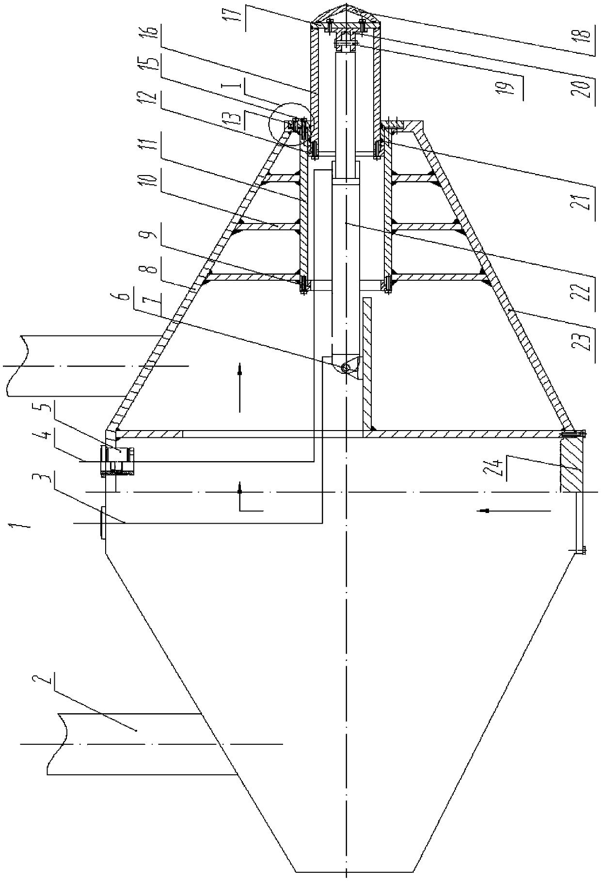
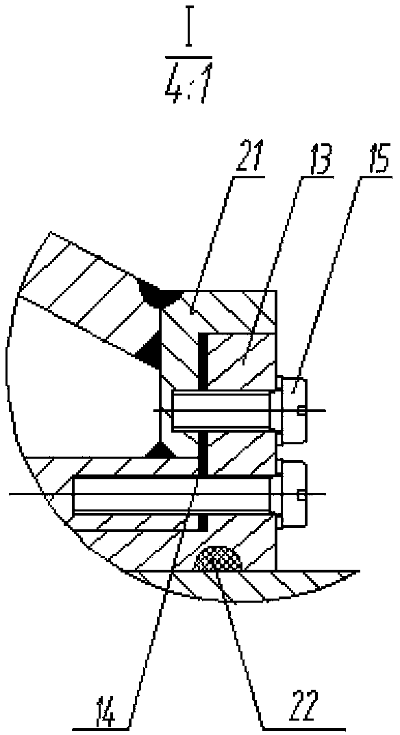
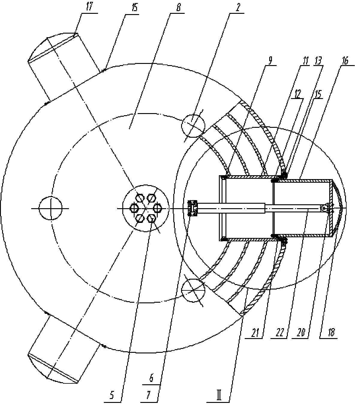
[0025] Such as figure 1 , 2 , 3, and 4, an anti-overturning jack-up platform pile shoe 1 is fixedly connected to the lower end of the pile leg 2, and includes an upper top plate 8, a lower bottom plate 23, and inner circumferential and radial reinforcement ribs 10 A'discus-shaped' shell; the'discus-shaped' shell contains at least three halves placed horizontally and radially along its circumferential side wall, and can be extended and retracted. The front end of the shell is closed and the rear end is equipped with an outer stop The telescopic tube 16 of the ring 12 and the tubular slide 11 in the casing for guiding the telescopic tube 16 and welded to the ribs 10 inside the casing; the inner and outer openings of the slide 11 are connected by bolts 15 respectively. The flange ring 9, 13 is used to provide a limit when the telescopic tube 16 is telescopic; the inner circumference of the limit flange 13 is provided with a sealing ring 21, and the inner end of ...

Example Embodiment

[0032] Example two

[0033] Such as Image 6 On the basis of the first embodiment, a telescopic tube 32 is added between the telescopic tube 16 and the tubular slide 11 of the first embodiment. The rear end of the telescopic tube 32 is fixedly installed with a limit stop ring 31, the front end is installed with an elliptical limit flange 34, and the telescopic tube 16 is sleeved inside to ensure the smooth sliding of the telescopic tube 16 and provide The telescopic limit restricts its sliding stroke; wherein, the inner circumferential surface of the limit flange 34 is provided with a sealing ring 35, and its function is the same as the limit flange 13 and the limit flange 13 and the outer mouth of the tubular slide 11 in the first embodiment. The function of the sealing ring 21 is the same. When the present invention with one telescopic tube has the same effect as the pile shoe with only one telescopic tube, the length of the tubular slide 11 will be shortened, thereby saving ...


PUM


Abstract

The invention discloses an overturn-resistant self-elevating platform pile shoe which comprises an iron-plate-shaped hollow flat circular shell body connected by an upper top board and a lower bottom board. At least three tubular sliding ways fixedly connected with the shell body are horizontally arranged along the circumference wall of the shell body in an equally spaced mode; the front end of each tubular sliding way is provided with a limiting ring and a sealing ring, the rear end of each tubular sliding way is provided with a flange, a hydraulic oil cylinder and at least one section of telescopic pipe are sequentially arranged from the rear end to the front end, one end of a piston rod of the hydraulic oil cylinder is connected with a reinforced bar inside the shell body, a rod head arranged at the other end of the piston rod is connected with the inner end face of the front end of the telescopic pipe, the front end of the telescopic pipe is closed, and the rear end of the telescopic pipe is provided with a flange; the upper top board of the shell body is further provided with a watertight stuffing box, a watertight door is arranged at the bottom of the lower bottom board, and the hydraulic oil cylinder is communicated with a hydraulic servo system installed on a self-elevating platform through a high-pressure oil pipe. The overturn-resistant self-elevating platform pile shoe has the advantages of being flexible in operation, safe, reliable, resistant to overturning and sliding and strong in puncturing capacity.

Description

technical field [0001] The invention relates to a self-elevating ocean platform equipment, in particular to a spud shoe applied to the self-elevating ocean platform. It belongs to the field of marine engineering machinery. Background technique [0002] The spud shoe is a device installed under the truss legs of the jack-up platform. Its function is to transmit the force of the legs to the seabed soil and support the entire platform through the legs. Due to the mechanical independence between the various spud cans of the platform, the platform supported by the spud can is more adaptable than the platform supported by the ground (sinking pad), which can work on uneven seabed or slightly inclined sea area. [0003] At present, under the conditions of soft seabed and deep pile insertion, the traditional spud can is similar to an enlarged "discus"; increasing its diameter improves the bearing capacity of the spud can, but it will make it difficult to lift the pile, and even the ...

Claims


Application Information

Patent Timeline
IPC IPC(8): E02D5/72E02B17/02
Inventor 唐文献何文生张建庄宏王亚坤孙海超高超齐继阳李金泰纪成冲卢崎
Owner JIANGSU UNIV OF SCI & TECH
Why Eureka
Try Eureka