Surface topography detector and method for use of the same

a topography detector and surface technology, applied in the field of surface topography detection technologies, can solve problems such as one difficulty always apparen

Inactive Publication Date: 2007-07-12
HON HAI PRECISION IND CO LTD
View PDF3 Cites 15 Cited by
  • Summary
  • Abstract
  • Description
  • Claims
  • Application Information

AI Technical Summary

Benefits of technology

[0006]In accordance with one embodiment, a surface topography detector includes a first sensor with a first central axis, a second sensor with a second central axis and a digital control unit. The angle defined between the first center axis and the second center axis is equal to or less than 90 degrees. The digital control unit is electrically connected with the first sensor and the second sensor and is configured for processing output signals from the first sensor and the second sensor and controlling movement of the first sensor and the second sensor.
[0007]In accordance with an embodiment, a method for detecting a surface topography of a workpiece includes the steps of: arranging a first sensor with a first central axis and a second sensor with a second central axis in a manner such that an angle is defined between the first center axis and the second center axis, the angle being equal to or less than 90 degrees; determining detecting locations of the first sensor and the second sensor; detecting the locations on the surface using the first sensor and the second sensor; and processing output signals from the first sensor and the second sensor thereby obtaining a result.
[0008]Other advantages and novel features of the present surface topography detector and method for detecting a surface topography of a workpiece will become more apparent from the following detailed description when taken in conjunction with the accompanying drawings.

Problems solved by technology

It is well known that lenses can be produced by injection molding, but one difficulty has always been apparent.

Method used


Image

  • Surface topography detector and method for use of the same
  • Surface topography detector and method for use of the same
  • Surface topography detector and method for use of the same

Examples


Embodiment Construction

[0012]Embodiments of the present surface topography detector and method for detecting a surface topography of a workpiece will now be described in detail below and with reference to the drawings.

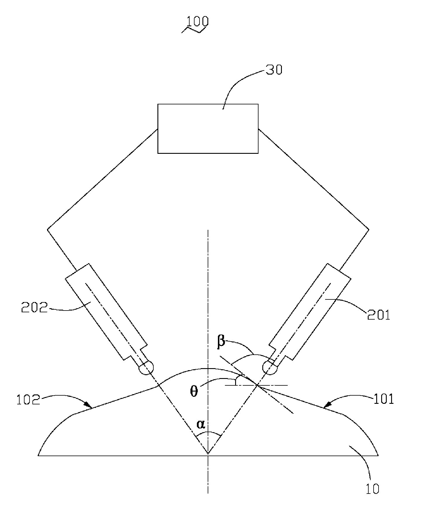
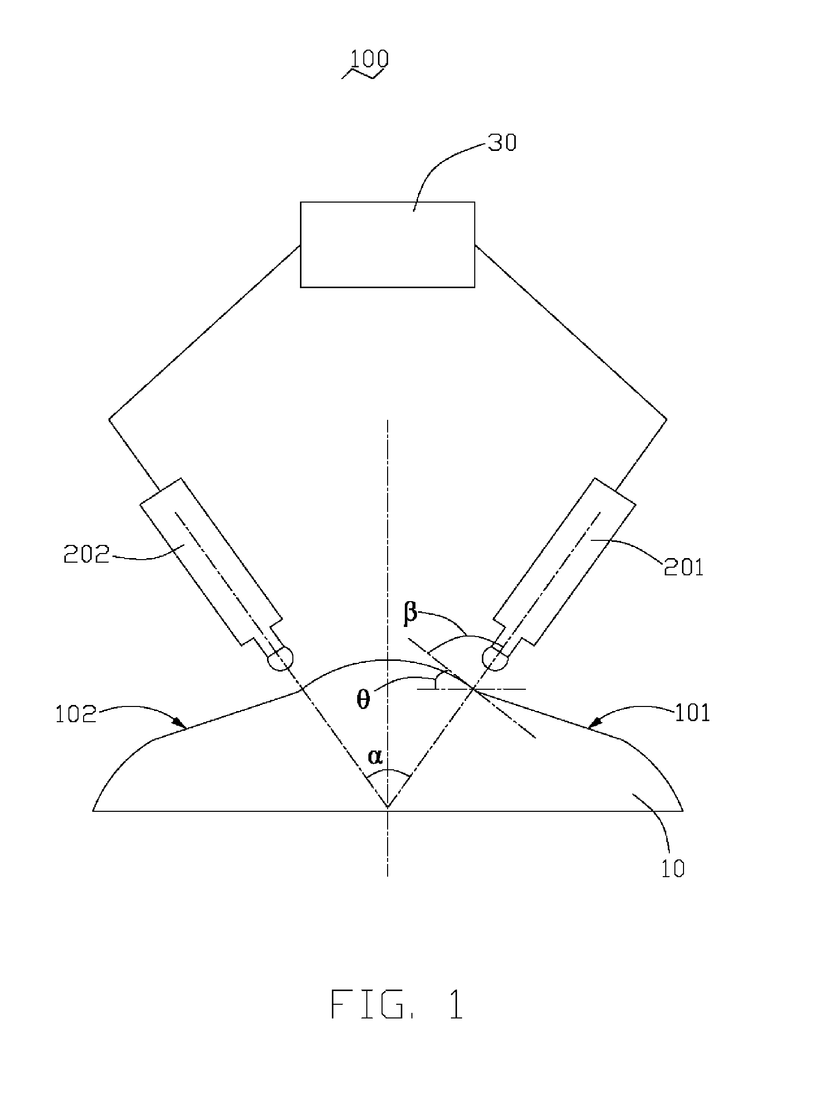
[0013]Referring to FIG. 1, a surface topography detector 100 according to a preferred embodiment includes a first sensor 201 with a first central axis, a second sensor 202 with a second central axis and a digital control unit 30. An angle α defined between the first center axis and the second center axis can be equal to or less than 90 degrees. The digital control unit 30 is electrically connected with the first sensor 201 and the second sensor 202. The digital control unit 30 is configured for processing output signals from the first sensor 201 and the second sensor 202 and controlling movement of the first sensor 201 and the second sensor 202.

[0014]The first sensor 201 and second sensor 202 can be optical interference sensors or inductive transducers. Preferably, the angle α defined betwee...


PUM


Abstract

A surface topography detector includes a first sensor, a second sensor and a digital control unit. The angle defined between the center axis of the first sensor and the center axis of the second sensor is equal to or less than 90 degrees. The digital control unit is electrically connected with the first sensor and the second sensor and is arranged for controlling the movement of the first sensor and the second sensor and processing the output signals of the first sensor and the second sensor. The surface topography detector can detect a surface with a bigger range of gradient angle accurately.

Description

FIELD OF THE INVENTION[0001]The present invention relates to surface topography detecting technologies and, more particularly, to a surface topography detector and a method for detecting surface topography of a workpiece.DESCRIPTION OF RELATED ART[0002]In recent years, mobile phones with cameras have been rapidly gaining in popularity. An aspherical lens used in mobile phone cameras can be as thin as about 1 mm whilst requiring a surface precision of about ±1 μm.[0003]It is well known that lenses can be produced by injection molding, but one difficulty has always been apparent. In order to produce lenses with the desired level of precision, the molds used in the injection molding require an equally high level of precision.[0004]Referring to FIG. 2, in a related surface topography machining process for an aspherical workpiece, a surface topography detector is usually used to detect surface topography of the aspherical workpiece. A conventional surface topography detector includes a s...

Claims


Application Information

Patent Timeline
Patent Type & Authority Applications(United States)
IPC IPC(8): G01B5/20G01B5/012
CPCG01B7/287
Inventor CHIU, WEN-SSU
Owner HON HAI PRECISION IND CO LTD
Why Eureka
Try Eureka