Chair with automatci regulated back

A backrest and chair technology, applied in the field of chairs with automatic backrest movement and adjustment, can solve the problems of spine burden, upper body leaning comfortably and safely on the backrest, and easy to feel fatigue, so as to protect the spine and benefit the health of the body

Inactive Publication Date: 2009-11-04
MANPLUS
View PDF7 Cites 7 Cited by
  • Summary
  • Abstract
  • Description
  • Claims
  • Application Information

AI Technical Summary

Problems solved by technology

If you sit on a chair for a long time and work in such a posture, you will not be able to comfortably and safely lean your upper body on the backrest, so you will easily feel tired, and even cause serious diseases such as lumbar discs due to the serious burden on the spine.

Method used


Image

  • Chair with automatci regulated back
  • Chair with automatci regulated back
  • Chair with automatci regulated back

Examples


Embodiment Construction

[0025] specific implementation

[0026] Embodiments of the present invention will be described below in conjunction with the accompanying drawings.

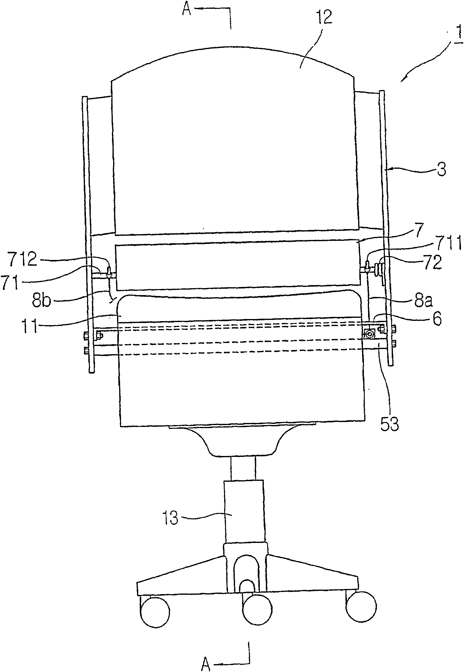
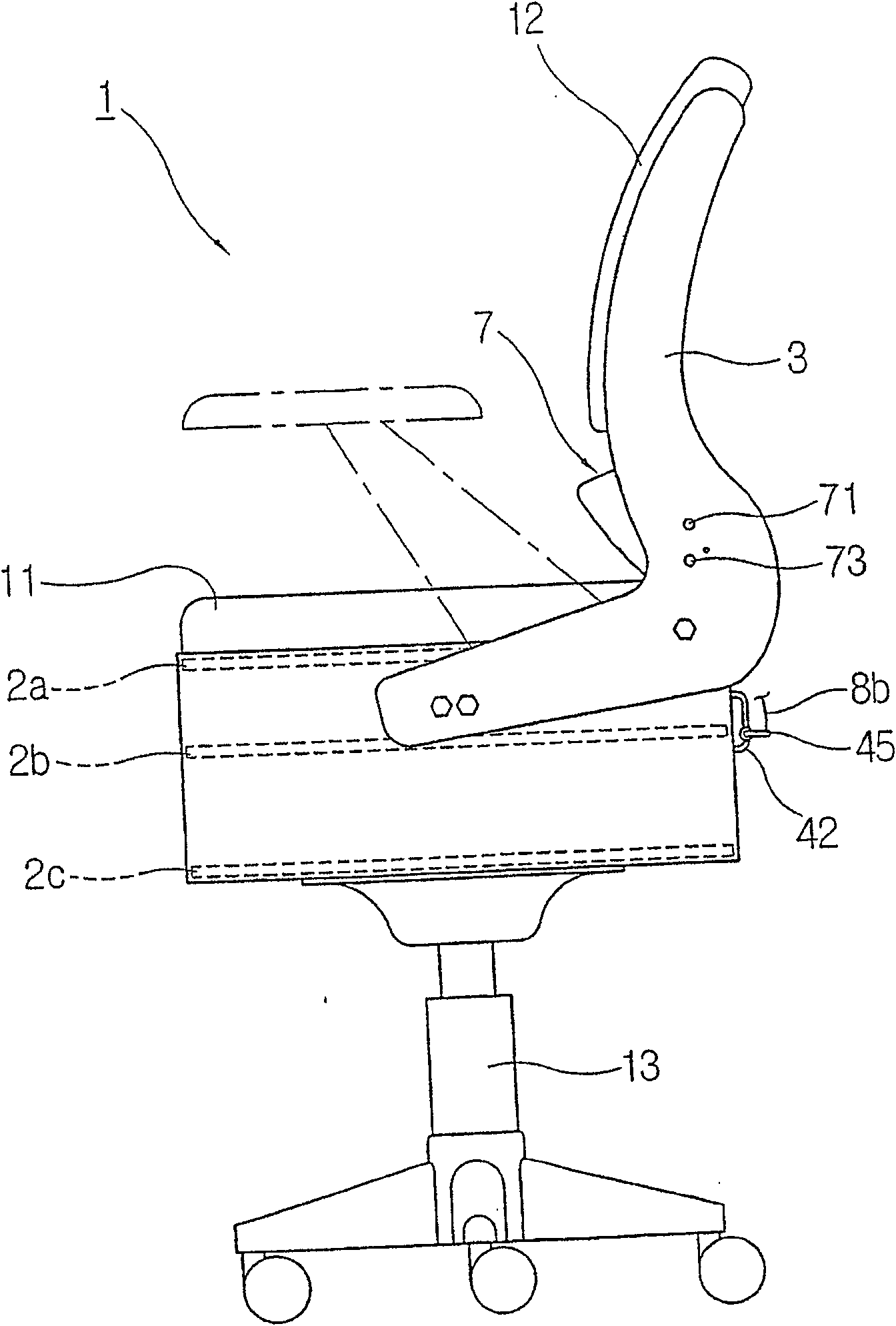
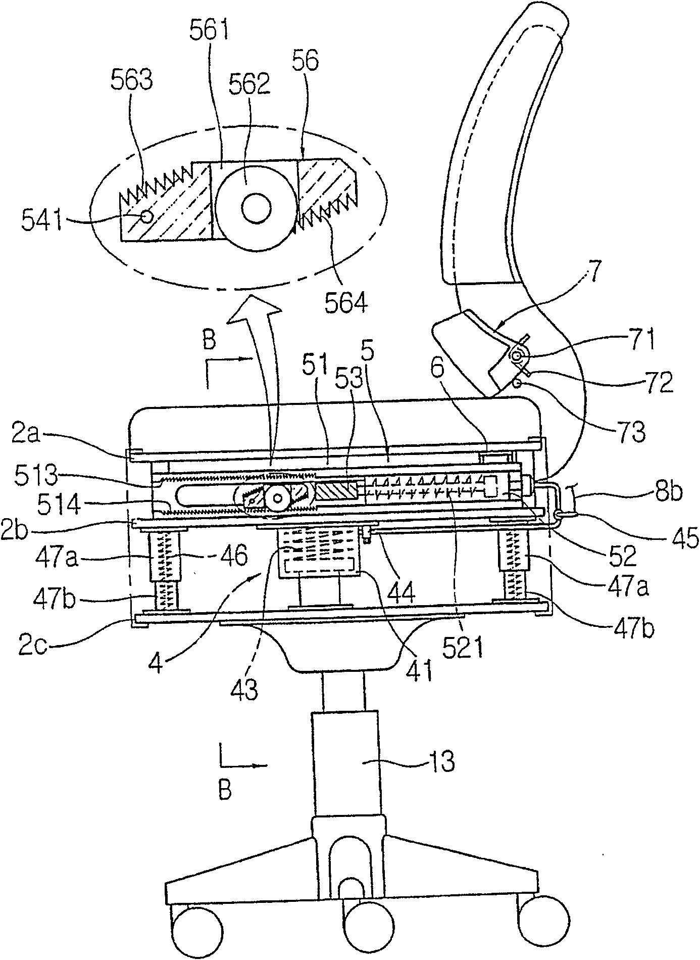
[0027] figure 1 and figure 2 It is the front and side views of the present invention; image 3 for figure 1 A-A line sectional view of ; Figure 4 is a partially isolated perspective view of the main part shown for the purpose of illustrating the present invention; Figure 5 In order to illustrate the present invention, the seat cushion and the upper frame are disassembled, and the plan view showing the arrangement state of each component in the middle frame and the connection state between the backrest frames; Figure 6 for image 3 B-B line sectional view; Figure 7 to Figure 9 It is a sectional view of the backrest action state of the present invention; Figure 10 It is a cross-sectional view of another embodiment of the present invention.

[0028] Reference numeral 1 denotes a chair, and the chair 1 is composed of a...


PUM


Abstract

The invention relates to the technology of a chair whose backrest can be automatically moved and adjusted. The chair of the present invention includes a seat cushion, a backrest, and a support leg, and is composed of an upper plate, a middle plate, and a lower plate, which face up and down at a predetermined interval while being kept disposed between the seat cushion and the support leg. Arrangement; a hydraulic booster composed of a hydraulic booster cylinder, wherein the hydraulic booster cylinder is arranged between the middle plate and the lower plate, and performs elastic buffering action against the force from the upper and lower directions, that is, when the user sits on the seat cushion When going up, based on the user's weight, the middle plate is elastically compressed, and the hydraulic release is delivered to the reciprocating action cylinder set between the upper plate and the middle plate. state, and absorb the hydraulic pressure delivered to the above-mentioned cylinder; the guide box, which is located between the upper plate and the middle plate, is fixed on the top of the middle plate facing the front-rear direction; the reciprocating action cylinder is horizontally arranged inside the guide box, when When the hydraulic booster cylinder of the hydraulic booster releases the hydraulic pressure, the piston rod moves forward with the inflow of the hydraulic pressure. When the hydraulic pressure is recovered from the hydraulic booster cylinder, the piston rod retreats with the release of the hydraulic pressure; The formed backrest moving part is installed horizontally through the moving long holes on the left and right sides of the guide box, and passes through the guide box in a vertical cross direction. At the same time, it is connected to the front end of the piston rod of the reciprocating cylinder. The forward and backward movements of the guide box are carried out within the moving range of the moving long hole of the guide box; the backrest frame, which is connected to both ends of the main joystick of the backrest moving part, performs forward or backward actions together with the main joystick; The sub joystick is movably provided at the rear between the upper board and the middle board, and both ends thereof perform forward or backward motions together with the backrest frame in a state of being connected to the backrest frame.

Description

technical field [0001] The present invention relates to the technology of a chair whose backrest can be automatically moved and adjusted. More specifically, it relates to a chair provided with supporting legs which can move on the ground, and various chairs such as seat cushions which are movably and adjustablely installed in the interior of a car. Even if the user sits on the cushion with his back not leaning against the backrest, the backrest of the chair will automatically move according to the weight of the user, and then support the user's back, so that the user can sit on the chair with a correct posture, effectively Protect the user's spine. Background technique [0002] In schools, cram schools, libraries or public institutions, corporate offices and conference rooms, people who use desks or desks to study or work will sit on chairs to study or work, and in order to make users feel comfortable, most of the chairs All have backrests. [0003] Generally speaking, the...

Claims


Application Information

Patent Timeline
IPC IPC(8): A47C1/024A47C7/46
CPCA47C1/03255A47C1/03294A47C7/35A47C7/62A47C1/03274
Inventor 李宗澔
Owner MANPLUS
Why Eureka
Try Eureka