Plastic rubber gas-blowing foaming injection machine for footwear

A technology of air blowing and foaming and injection machines, which is applied in applications, household components, household appliances, etc., and can solve problems such as the decline in the qualified rate of products, easy discoloration of sole products, and unfavorable production

Inactive Publication Date: 2009-11-18
SHANGHAI DRB & TAFU IND
View PDF5 Cites 0 Cited by
  • Summary
  • Abstract
  • Description
  • Claims
  • Application Information

AI Technical Summary

Problems solved by technology

One is that the mold is fixed on the rotary disc, and the nozzle is injected from the back of the jaw of the jaw-type mold clamping mechanism. Lower clamping
Due to the limitation of the height of the nozzle, the height of the mold cannot be changed, which increases the difficulty of manufacturing molds for various styles and specifications of shoe sole products, which is not conducive to the production of many varieties and styles of shoe products in the current market; 2. Because the nozzle is from the back of the jaw If the screw barrel is too long, the material in the screw barrel will be overheated during pre-molding, which will easily cause overheating of the material, easy discoloration of the sole product, and a high rate of defective products; 3. Because the nozzle screw barrel is caught in the mold In the middle of the support plate of the mechanism, it brings inconvenience to operation, repair and maintenance
The other is that the screw barrel screw is set above the gantry-type mold clamping mechanism. The disadvantage is: due to the influence of the screw radius and the thickness of the upper template, the material channel and nozzle of the discharge port are lengthened a lot. After the injection is completed, When the mold is opened and turned, it is easy to produce cold material in the nozzle and the material channel. When the next mold is injected, the pass rate of the product will drop. Therefore, it is the concern of every customer in the market to solve the shortcomings of the above machines. Where to pursue

Method used


Image

  • Plastic rubber gas-blowing foaming injection machine for footwear
  • Plastic rubber gas-blowing foaming injection machine for footwear

Examples


Embodiment Construction

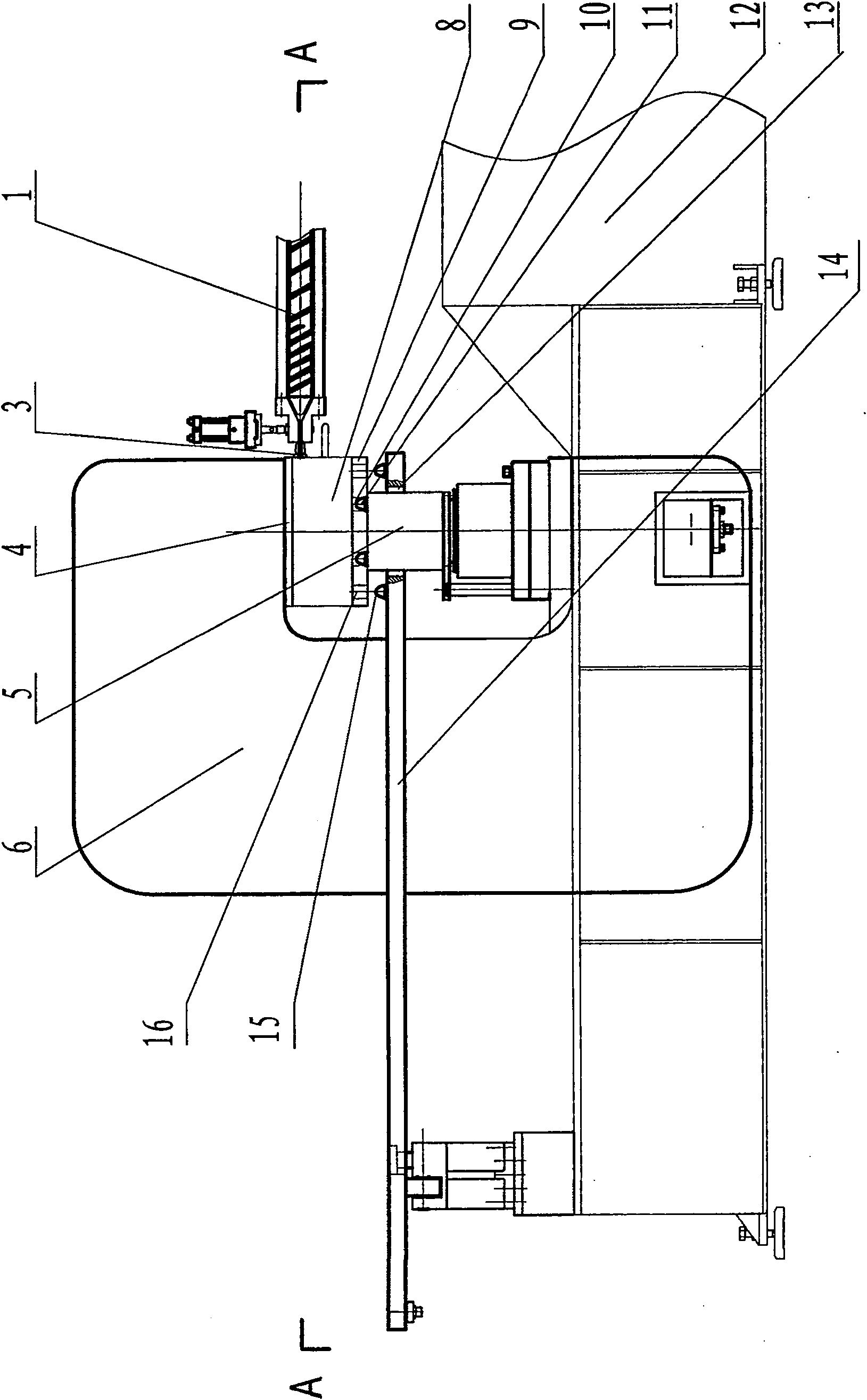
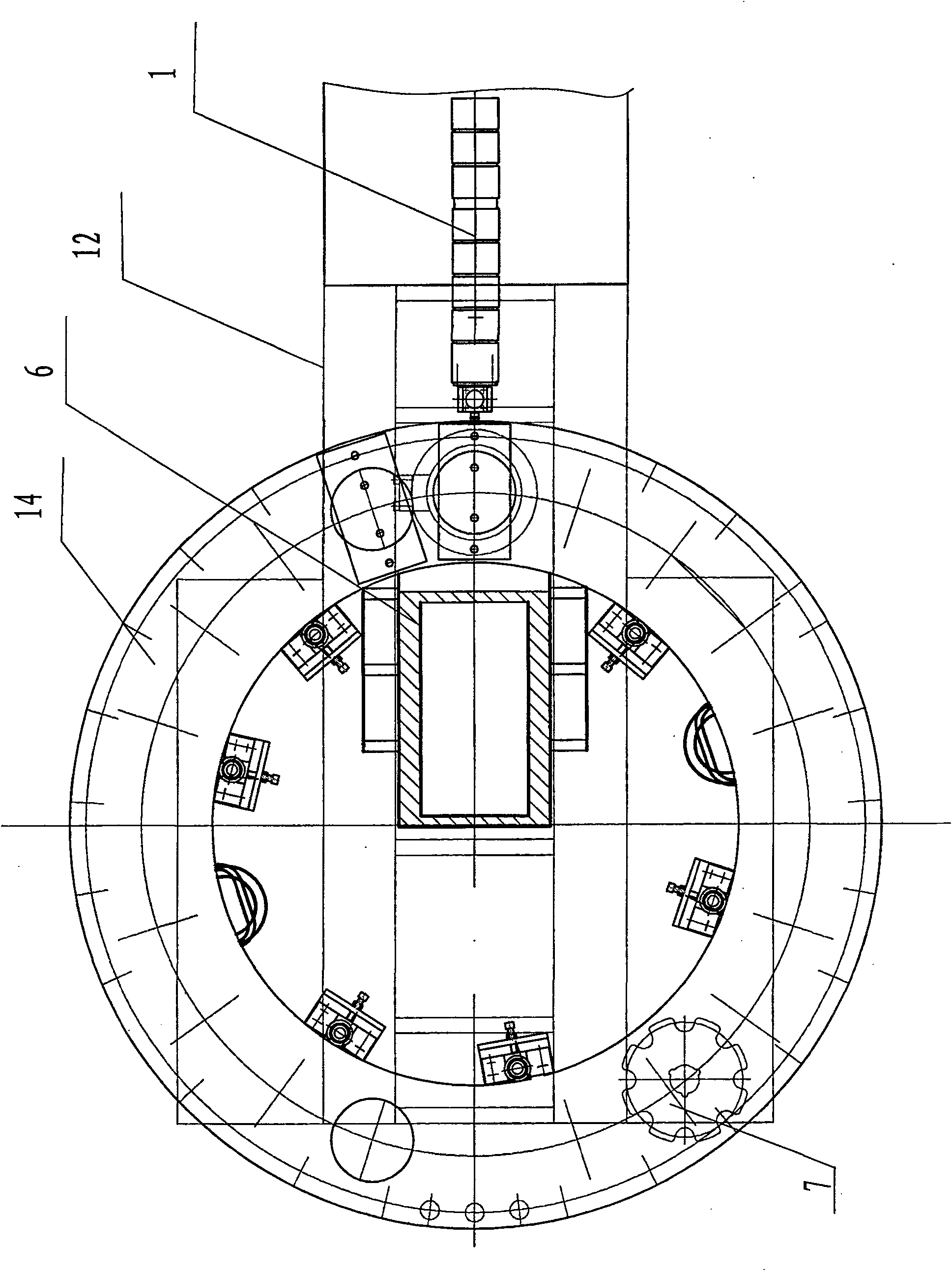
[0008] Such as figure 1 , figure 2 As shown, the present embodiment includes an injection mechanism 1, a mold clamping mechanism, a turntable 14, a rotary disc mechanism 7, and a frame 12, wherein the mold clamping mechanism includes a mold clamping pressurized cylinder 5, a jaw type clamping mold support 6, and injection The nozzle 3 in the mechanism is set opposite to the jaw end of the jaw-type clamping mold support, and the clamping pressurized cylinder 5 is arranged under the turntable 14 and placed on the lower surface of the jaw of the jaw-type clamping mold support 6. The mold clamping booster cylinder 5 corresponding turntable 14 is provided with the mold clamping booster cylinder 5 moving channels 13, the turntable 14 is provided with a mold positioning plate 9, and a positioning device (15, 16), a positioning connection device (10, 11) is provided between the mold positioning plate 9 and the clamping pressurized cylinder 5, and a mold cover plate 4 is provided on ...


PUM


Abstract

The invention relates to production equipment for producing plastic shoe soles, in particular to a plastic blowing and foaming injection machine for shoes. It includes an injection mechanism, a mold clamping mechanism, a turntable, and a rotary disc mechanism. The mold clamping mechanism includes a mold clamping pressurized cylinder, a jaw-type clamping bracket, a nozzle in the injection mechanism and a jaw-type clamping bracket. The mouth end is facing the setting. Its purpose is to design a plastic air-blowing foaming injection molding machine for shoes that can improve the qualified rate of products and is convenient for maintenance. Compared with the prior art, the invention has the advantages of improving the quality of sole products, saving raw materials, more widely adapting to the production needs of different product varieties, and the like.

Description

technical field [0001] The invention relates to production equipment for producing plastic shoe soles, in particular to a plastic blowing and foaming injection machine for shoes. Background technique [0002] There are two structural forms of plastic blowing and foaming injection machines for shoes that are commonly used in the Chinese market (including those made in Taiwan). One is that the mold is fixed on the rotary disc, and the nozzle is injected from the back of the jaw of the jaw-type mold clamping mechanism. Lower the mold. Due to the limitation of the height of the nozzle, the height of the mold cannot be changed, which increases the difficulty of manufacturing molds for various styles and specifications of shoe sole products, which is not conducive to the production of many varieties and styles of shoe products in the current market; 2. Because the nozzle is from the back of the jaw If the screw barrel is too long, the material in the screw barrel will be overhea...

Claims


Application Information

Patent Timeline
Patent Type & Authority Patents(China)
IPC IPC(8): B29C45/06B29C45/17B29L31/50
Inventor 叶孙勇
Owner SHANGHAI DRB & TAFU IND
Why Eureka
Try Eureka