
Radio transmission apparatus

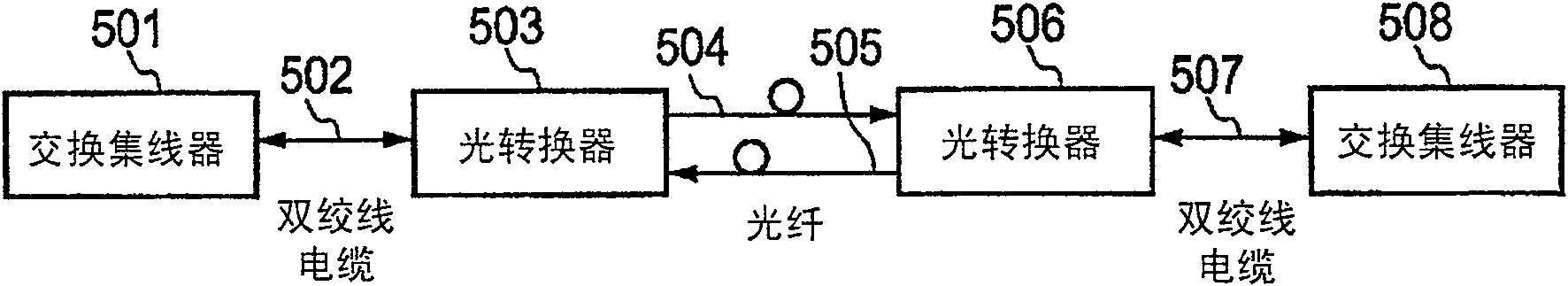
A technology of radio transmission and wired transmission, which is applied in the direction of radio transmission system, transmission system, wireless communication, etc., and can solve the problem that the twisted pair cable 507 cannot be restored to the normal state, etc.

Inactive Publication Date: 2009-11-25
NEC CORP
View PDF5 Cites 0 Cited by
  • Summary
  • Abstract
  • Description
  • Claims
  • Application Information

AI Technical Summary

Problems solved by technology

Therefore, the control of the link disconnection of the twisted pair cable 502 and the control of the twisted pair cable 507 are alternately repeated, and this causes a problem such that the twisted pair cable 502 and the twisted pair cable 507 cannot be restored to a normal state.

Method used


Image

  • Radio transmission apparatus
  • Radio transmission apparatus
  • Radio transmission apparatus

Examples


Embodiment Construction

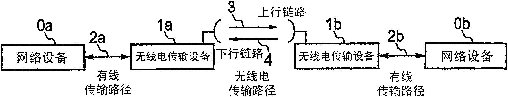
[0026] Hereinafter, the best mode for carrying out the present invention will be described. figure 2 is a block diagram showing an embodiment of the present invention. according to figure 2 In the illustrated embodiment, LAN signals received from a wired transmission path are transmitted one-to-one to a counterpart station via a radio transmission path.

[0027]The radio transmission devices 1 a and 1 b for outputting the LAN signal at the counterpart site again to the wired transmission path are opposed to each other via the radio transmission paths 3 and 4 . The radio transmission devices 1a and 1b have the same structure. The sections 11b to 19b, 51b to 61b configuring the radio transmission device 1b correspond to each of the sections 11a to 19a, 51a to 61a configuring the radio transmission device 1a. Here, the structure of the radio transmission device 1a will be described in detail.

[0028] exist figure 2 Among them, the LAN signal termination circuit 11a can e...


PUM


Abstract

The present invention provides the function of forcibly disconnecting the data links of the wired transmission paths respectively connected to two radio transmission devices opposing each other through the radio transmission path if link interference occurs in either the uplink or the downlink. path, and if the link of any one of the wired transmission paths respectively connected to the radio transmission equipment opposite through the radio transmission path is disconnected, the data link of the wired transmission path connected to the other party's radio transmission equipment is disconnected.

Description

technical field [0001] The present invention relates to a radio transmission device in which an interface signal (hereinafter defined as a LAN signal) received from a wired transmission path and standardized by IEEE 802.3 is transmitted to a counterpart station by the radio transmission device on a one-to-one basis, and Output it again from the other party's station to the wired transmission path. Background technique [0002] Hereinafter, the background art of the radio transmission apparatus described above will be described below. Meanwhile, JP-A-2000-324153 relates to this background art as a prior art document. Please refer to this document if necessary. [0003] In normal LAN data communication, two-way communication should be established. Therefore, when interference occurs in any one of the transmission and reception radio transmission paths in a network using a radio transmission path as a part of the transmission path to transmit and receive LAN signals, it is n...

Claims


Application Information

Patent Timeline
Patent Type & Authority Patents(China)
IPC IPC(8): H04L12/46H04B7/00H04W76/06
CPCH04W76/06H04W76/30H04B7/24
Inventor 齐藤嘉一郎
Owner NEC CORP
Learn More