Supercharge Your Innovation With Domain-Expert AI Agents!

Vacuum cleaner with a cover release element

A technology for vacuum cleaners and components, which can be used in vacuum cleaners, household appliances, cleaning equipment, etc., and can solve the problem that buttons cannot be used to lift and pull rice cookers

Inactive Publication Date: 2009-12-16
BSH BOSCH & SIEMENS HAUSGERAETE GMBH
View PDF6 Cites 0 Cited by
  • Summary
  • Abstract
  • Description
  • Claims
  • Application Information

AI Technical Summary

Problems solved by technology

[0008] The disadvantage of this prior art is that on the one hand the button for opening the lid is a separate component and on the other hand neither the button nor the lid itself can be used to lift the rice cooker

Method used


Image

  • Vacuum cleaner with a cover release element
  • Vacuum cleaner with a cover release element
  • Vacuum cleaner with a cover release element

Examples


Embodiment Construction

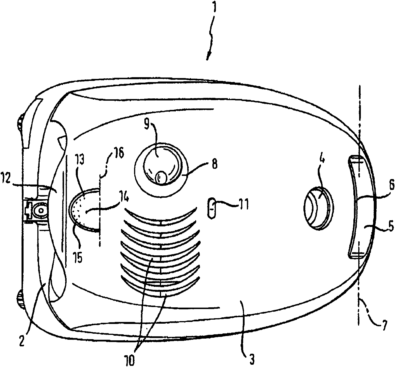
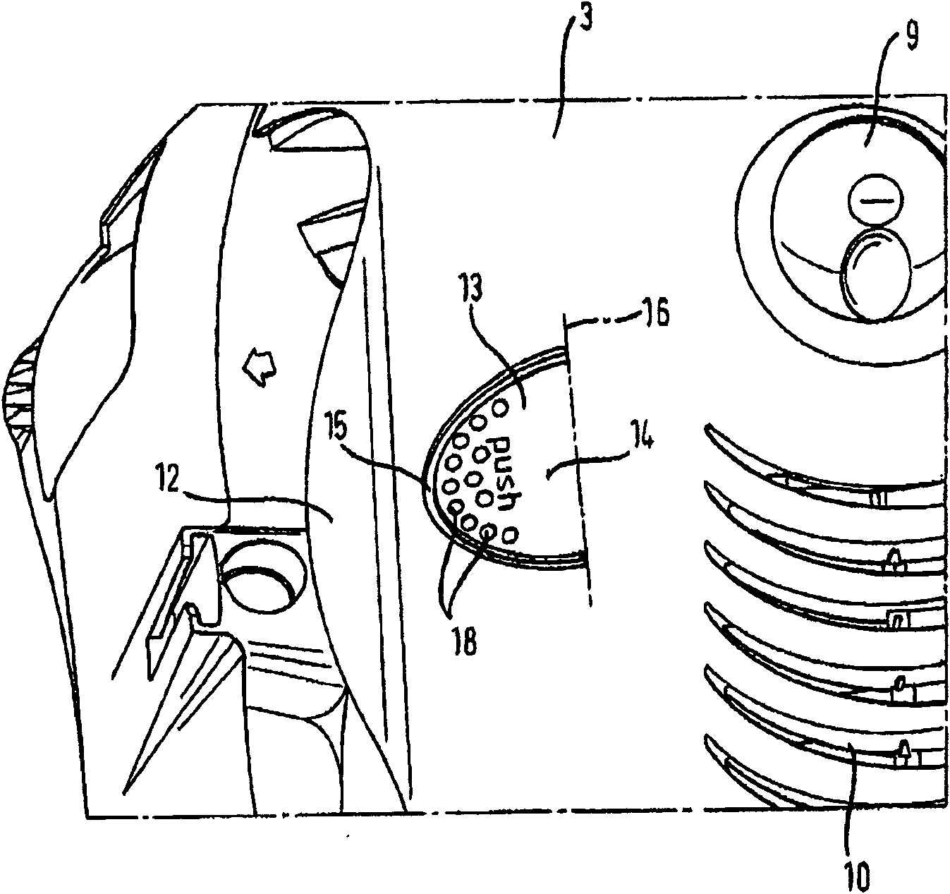
[0028] exist figure 1 The vacuum cleaner 1 shown in plan view in FIG. 2 has a housing 2 which is closed by a dust chamber cover 3 . A suction opening 4 is arranged in the dust collection chamber cover 3 , through which the air mixed with dust is sucked by the suction nozzle through the suction pipe and / or the suction hose. The suction port 4 is used to couple a hose connector (not shown). In the vicinity of the suction opening 4 a handle 5 is molded into the dust chamber cover 3 . The handle 5 is arcuately shaped and defines a handle opening 6 provided in the dust chamber cover 3, the handle opening being positioned and sized for the passage of four fingers of one hand. The dust chamber cover 3 is arranged pivotably about a pivot axis 7 on the housing 2 . The pivot axis 7 extends substantially parallel to the longitudinal extent of the handle 5 . In addition to being provided with a suction port 4, the dust collection chamber cover 3 also has another circular through hole ...


PUM


Abstract

The cleaner has a housing arranged with a dust accumulator, which is covered by a dust cavity cover (3). An unlocking unit (13) for a stop unit is provided at the cover as a single piece. The stop unit cooperates with a degenerating unit of the housing to hold the cover in a closed position. The unlocking unit is integrated into the outline of the cover, and is opened by pressing it.

Description

technical field [0001] The invention relates to a vacuum cleaner. The vacuum cleaner has a housing in which a dust collection chamber is arranged, the dust collection chamber can be closed by means of a dust collection chamber cover, on which an unlocking element for a clamping element is arranged, the clamping element is connected to the housing The mating clamping elements of the co-operate to hold the dust chamber lid in the locked position, wherein the unlocking element is integrated surface-flush into the contour of the dust chamber lid and is released by pressing. Background technique [0002] The commercially available vacuum cleaner disclosed in DE19804621B4 has a housing in which a dust chamber is arranged, which can be closed off by a dust chamber cover which has a plate-shaped (stegartig) handle area A section for manually lifting the vacuum cleaner, the handle section adjoins a recess of the dust chamber cover, into which the unlocking element of the clamping el...

Claims


Application Information

Patent Timeline
Patent Type & Authority Patents(China)
IPC IPC(8): A47L9/00
CPCA47L9/00A47L5/362
Inventor J·施罗特T·塞思
Owner BSH BOSCH & SIEMENS HAUSGERAETE GMBH
Features
  • R&D
  • Intellectual Property
  • Life Sciences
  • Materials
  • Tech Scout
  • Unparalleled Data Quality
  • Higher Quality Content
  • 60% Fewer Hallucinations
Learn More