Method for identifying transformer inner echo surge current

A transformer and phase current technology, applied in the field of relay protection of the main equipment of the power system, can solve the problems of inability to differentially protect the braking effect, the effect is not very good, and the content of the third harmonic is low.

Inactive Publication Date: 2009-12-16
TSINGHUA UNIV
View PDF2 Cites 0 Cited by
  • Summary
  • Abstract
  • Description
  • Claims
  • Application Information

AI Technical Summary

Problems solved by technology

However, the former will lower the sensitivity of differential protection, especially not conducive to the action of short-circuit fault protection between small turns; the latter has been researched and shown that it cannot eliminate the path of inrush current, and cannot avoid the generation of inrush current and the failure of differential protection of transformers. Misuse
According to the phenomenon that the current transformer saturation is more likely to cause the differential protection to malfunction when the inrush current is generated, it has been proposed to increase the current transformer saturation criterion to prevent the differential protection from malfunctioning, which improves the reliability of the differential protection to a certain extent. However, the third harmonic current transformer saturation criterion currently used has unreliable shortcomings. In practice, the third harmonic content may be low when the differential protection malfunctions, and it cannot play a braking role on the differential protection.
[0004] At present, there is no specific detection criterion for inrush current and corresponding differential protection anti-maloperation measures, but the excitation inrush current (mainly for the initial inrush current generated by transformer no-load closing) criterion and the current transformer saturation criterion are used. According to data, when the inrush current is generated, the blocking differential protection is not very effective in practice.

Method used


Image

  • Method for identifying transformer inner echo surge current
  • Method for identifying transformer inner echo surge current
  • Method for identifying transformer inner echo surge current

Examples


Embodiment Construction

[0019] The principle and specific implementation of the present invention will be described below in conjunction with the accompanying drawings.

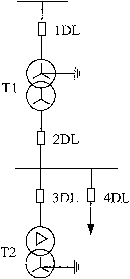
[0020] figure 1 Transformer cascade operation wiring diagram. The transformer T1 is in a normal operating state, and at a certain moment, the transformer T2 is closed with no load. The initial excitation inrush current will be generated in the no-load closing transformer, and the inrush current phenomenon will be generated in the running transformer.

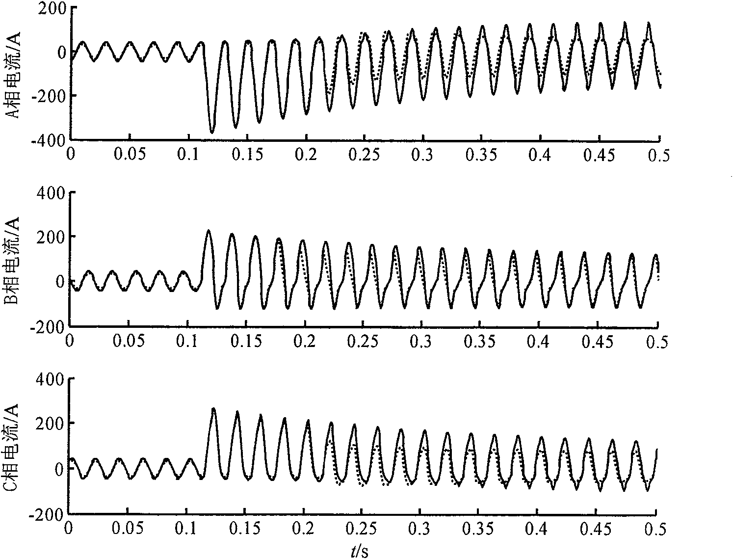
[0021] figure 2 is the phase current on both sides of the operating transformer T1 in the embodiment of the present invention. After the transformer T2 is closed with no load, the winding phase current measured by the current transformers on both sides of the transformer T1 (converted to the primary side), it can be seen from the figure that the secondary side current transformer is saturated. Seriously saturated.

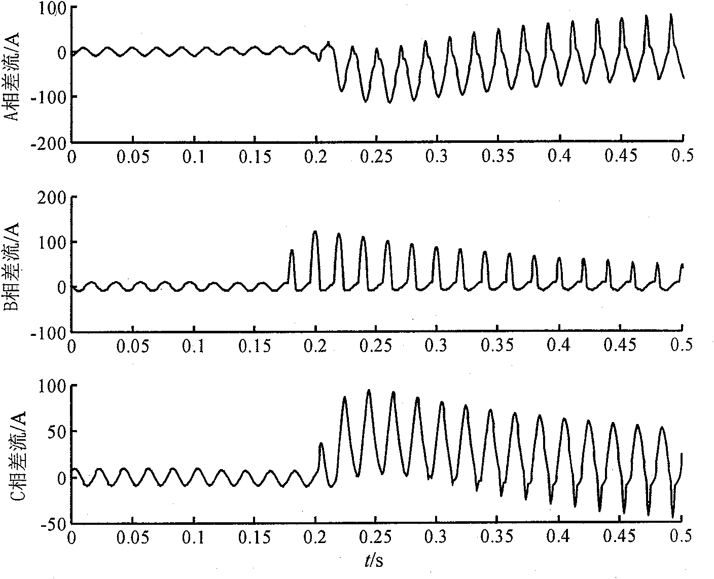
[0022] image 3 is the differential current of the phase curre...


PUM


Abstract

A method for identifying inrush current in a transformer belongs to the technical field of relay protection for main equipment in a power system. According to the transformer and the cause of the inrush current, use a computer to collect the phase current and phase voltage of the primary and secondary windings of the running transformer, and calculate the difference between the primary and secondary phase currents, that is, the differential current; In the calculation period, the unsaturated operating area is determined according to the maximum value of the absolute value of the differential current; then the equivalent instantaneous inductance in the unsaturated operating area is calculated, and the operation transformer is judged by the average value of the equivalent instantaneous inductance in the unsaturated area. Should surge current, block the differential protection to prevent its malfunction. Compared with the second harmonic ratio excitation inrush blocking criterion and the third harmonic ratio current transformer saturation criterion, this method has the advantages of high reliability and strong anti-current transformer saturation ability in identifying and responding to inrush current.

Description

technical field [0001] The invention belongs to the technical field of relay protection for main equipment of a power system, and in particular relates to a method for identifying transformers and inrush currents that should be excited. Background technique [0002] Transformer relay protection is the guarantee for its safe and stable operation, but in actual operation, due to the influence of many external conditions and its own principles, the correct action rate of the differential protection as the main protection has always been low. Among the many influencing factors, due to the no-load closing of a transformer, an inrush current is generated in an adjacent operating transformer, which leads to many instances of misoperation of the differential protection of the operating transformer. The misoperation phenomenon of differential protection is attracting the attention of the relay protection circle because of its harmfulness, complexity and concealment. [0003] Aiming ...

Claims


Application Information

Patent Timeline
Patent Type & Authority Patents(China)
IPC IPC(8): H02H7/045G01R19/165
Inventor 毕大强王祥珩王维俭
Owner TSINGHUA UNIV
Why Eureka
Try Eureka