Bidirectional movement vertical type steel-bar automatic bending machine

A two-way moving, bending machine technology, used in workpiece clamping devices, manufacturing tools, etc., can solve the problems of small positive and negative bending angle displacement, limited bending minimum size, easy to hurt the operator, etc., to achieve stable work, simple and easy operation. The effect of low cost of operation and processing

Active Publication Date: 2010-01-13
TJK MACHINERY TIANJIN
View PDF5 Cites 0 Cited by
  • Summary
  • Abstract
  • Description
  • Claims
  • Application Information

AI Technical Summary

Problems solved by technology

[0006] 1. Since the height of the unloading rack is higher than that of the steel bar automatic bending machine, when manually placing the steel bar on the horizontal workbench of the steel bar automatic bending machine, it is necessary to move the steel bar down from a high place, and the material moving process is from top to bottom. Inconvenient to operate, easy to injure the operator
[0007] 2. Although the horizontal automatic steel bar bending machine in the prior art can bend in both directions, the minimum size of the bending is limited due to its oversized shape.
The minimum bending length of the horizontal automatic steel bar bending machine in the prior art is 1.5m; the positive and negative bending angle displacement is small, only ±90°; the operation process of the horizontal automatic steel bar bending machine in the prior art is complicated
[0008] 3. The prior art horizontal steel bar automatic bending machine includes a fixed bending machine and a mobile bending machine, the bending process takes a long time and the production efficiency is low

Method used


Image

  • Bidirectional movement vertical type steel-bar automatic bending machine
  • Bidirectional movement vertical type steel-bar automatic bending machine
  • Bidirectional movement vertical type steel-bar automatic bending machine

Examples


Embodiment Construction

[0019] Embodiments of the present invention will be further described below in conjunction with the accompanying drawings.

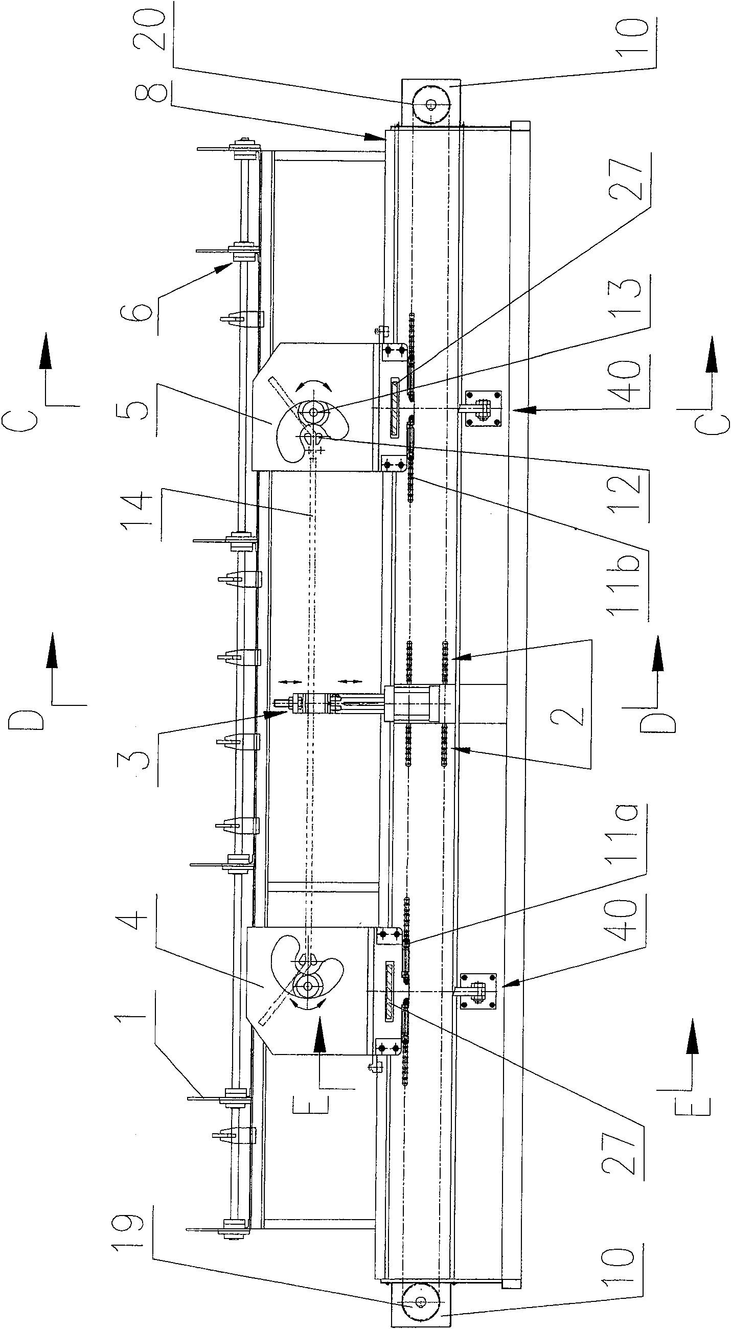
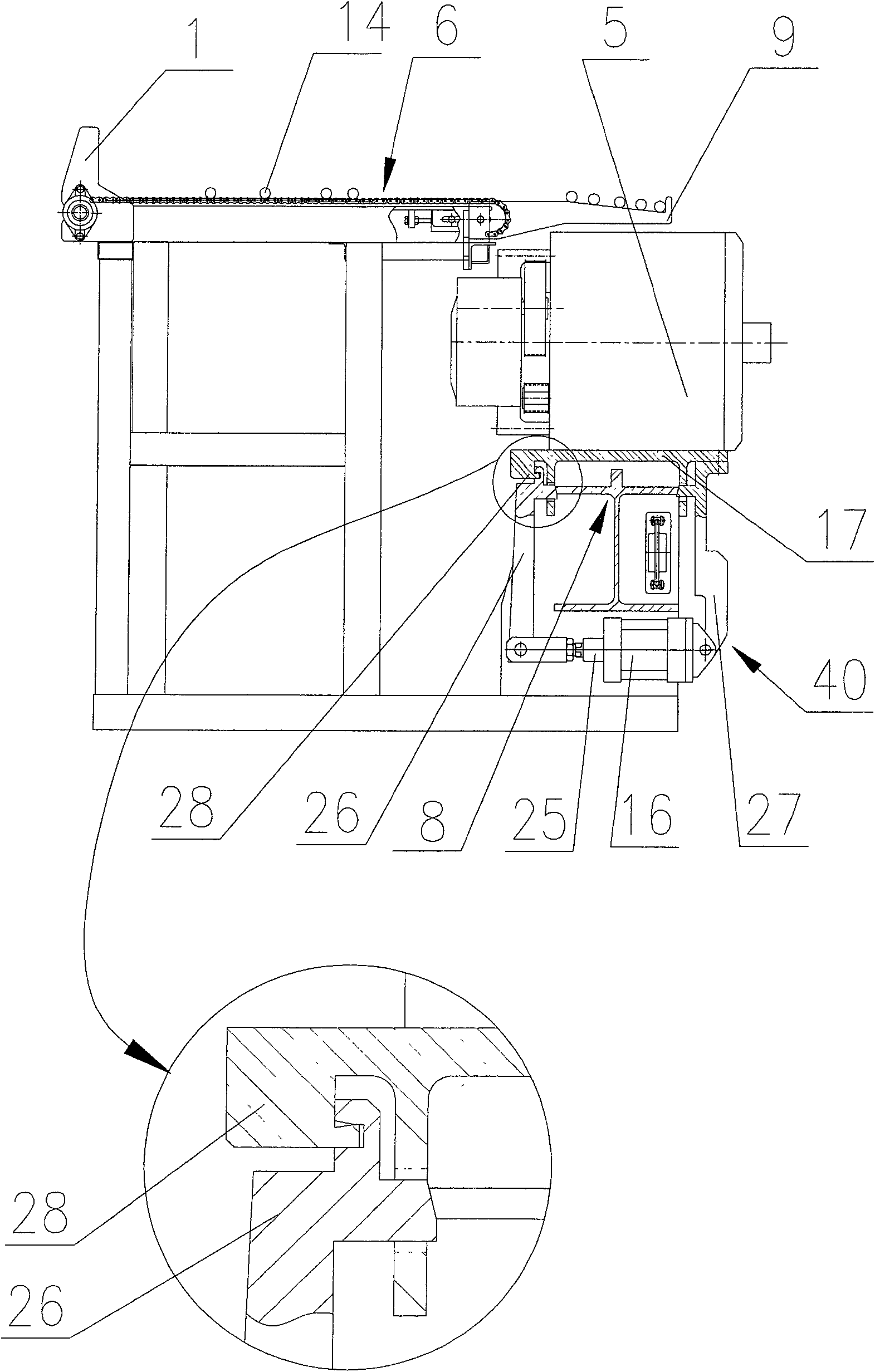
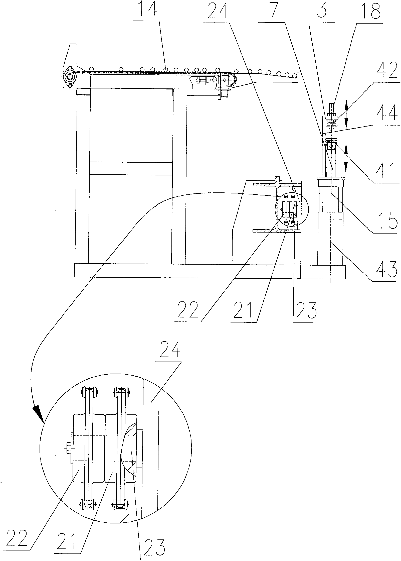
[0020] figure 1 is the front view of the present invention; figure 2 yes figure 1 Middle C-C sectional view; image 3 yes figure 1 Middle D-D sectional view; Figure 4 yes figure 1 Middle E-E sectional view.

[0021] The present invention provides a two-way mobile vertical automatic bending machine for steel bars. The two-way mobile vertical automatic steel bar bending machine includes: a track 8 , a steel bar automatic bending machine moving on the track 8 , and a steel bar pressing device 3 .

[0022] The steel bar pressing device 3 is arranged on one side of the track 8 .

[0023] The steel bar automatic bending machine includes the first steel bar automatic bending machine 4 and the second steel bar automatic bending machine 5 corresponding to the same structural position; the bottoms of the first steel bar automatic bending machine 4 and the...


PUM

PropertyMeasurementUnit
lengthaaaaaaaaaa

Abstract

The invention discloses a bi-directional movement vertical reinforcing steel bar automatic bending machine, which comprises a rail, an reinforcing steel bar automatic bending machine which moves on the rail and a reinforcing steel bar compressing device; the reinforcing steel bar compressing device is arranged on one side of the rail; the reinforcing steel bar automatic bending machine consists of a first reinforcing steel bar automatic bending machine and a second reinforcing steel bar automatic bending machine which have the same structure and arranged on corresponding positions; the bottoms of the first reinforcing steel bar automatic bending machine and the second reinforcing steel bar automatic bending machine are provided with bi-directional traction mechanisms which have the same structure and are used for driving the bending machines to move on the rail and locking mechanisms which are used for locking the bending machines on the rail. The invention has the beneficial effects that the vertical bending pattern is easier for operation and the safety of operator can be guaranteed. The minimum bending length is 460mm and the bending angle range is extended. The two bending machines can move right and left fast at the same time for bending reinforcing steel bars to shorten the bending and forming time and promote the productivity. The invention has the advantages that the structure is simple and maintenance is convenient; work is stable and the energy is saved and the cost is low.

Description

technical field [0001] The invention relates to an automatic bending machine for steel bars, in particular to a two-way mobile vertical automatic bending machine for steel bars. Background technique [0002] The automatic steel bar bending machine is a device that bends steel bars into squares, rectangles, triangles and other shapes. The automatic steel bar bending machine in the prior art has a horizontal structure, and a discharge rack supporting the sheared steel bar is arranged on one side of the automatic steel bar bending machine. The height of the discharge rack is higher than that of the automatic steel bar bending machine. [0003] The horizontal steel bar automatic bending machine includes: a track; a fixed bending machine fixed at one end of the track and a mobile bending machine moving on the track. The fixed bending machine includes: a chassis; a horizontal workbench arranged on the upper part of the chassis; the workbench is provided with: a bending mandrel, a...

Claims


Application Information

Patent Timeline
Patent Type & Authority Patents(China)
IPC IPC(8): B21F1/00B25B11/00
Inventor 陈振东
Owner TJK MACHINERY TIANJIN
Why Eureka
Try Eureka