
Driving control apparatus

A technology for driving transmission and control signals, applied in printing devices, control using feedback, printing, etc., can solve problems such as slow response speed and large speed control error, and achieve the goal of reducing speed error, increasing stability, and speeding up response speed Effect

Inactive Publication Date: 2010-01-13
PRIMAX ELECTRONICS LTD
View PDF7 Cites 0 Cited by
  • Summary
  • Abstract
  • Description
  • Claims
  • Application Information

AI Technical Summary

Problems solved by technology

[0005] The purpose of the present invention is to provide a drive control device to solve the shortcomings of the prior art, such as slow response speed and large speed control error

Method used


Image

  • Driving control apparatus
  • Driving control apparatus
  • Driving control apparatus

Examples


Embodiment Construction

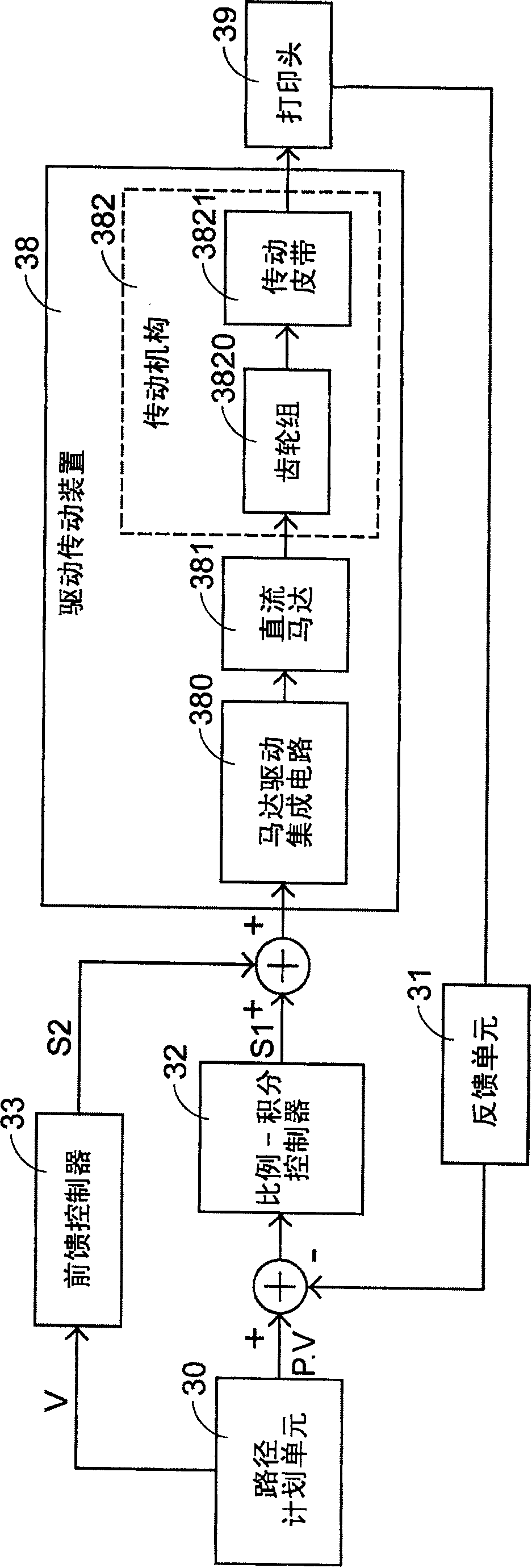
[0026] See image 3 , which is a functional block diagram of a preferred embodiment of an inkjet head driving control device that can improve the defects of the present invention and can be applied to an inkjet printer or an inkjet multifunction machine, which mainly includes a path planning unit 30 , a feedback unit 31, a proportional-integral controller 32 and a feedforward controller 33, wherein the path planning unit 30 is the same as the prior art, and it is used to output a position command value P and a speed command value V, and the feedback unit 31 is mainly based on The actual position and speed of the print head 39 generate a position feedback signal Pf and a speed feedback signal Vf, and the proportional-integral controller 32 is based on the difference Pd between the position command value P and the position feedback signal Pf and the speed command value V and The difference Vd of the speed feedback signal Vf generates the first control signal S1. The feed-forwar...


PUM


Abstract

The invention relates to a drive control device. It includes route planning unit used to output position and speed command values, feedback unit which is signal connection with the print head and used to generate position and speed feedback signal, proportional-integral controller which is signal connection with the route planning unit, feedback unit, and drive actuator, and used to generate the first control signal and send it to the drive actuator according to the difference between the command value and feedback signal, and feed forward control which is signal connection with the route planning unit and the drive actuator, used to receive speed command value to calculate, generate the second control signal, and transmit it to the drive actuator to drive the print head to move according to the first and second control signals.

Description

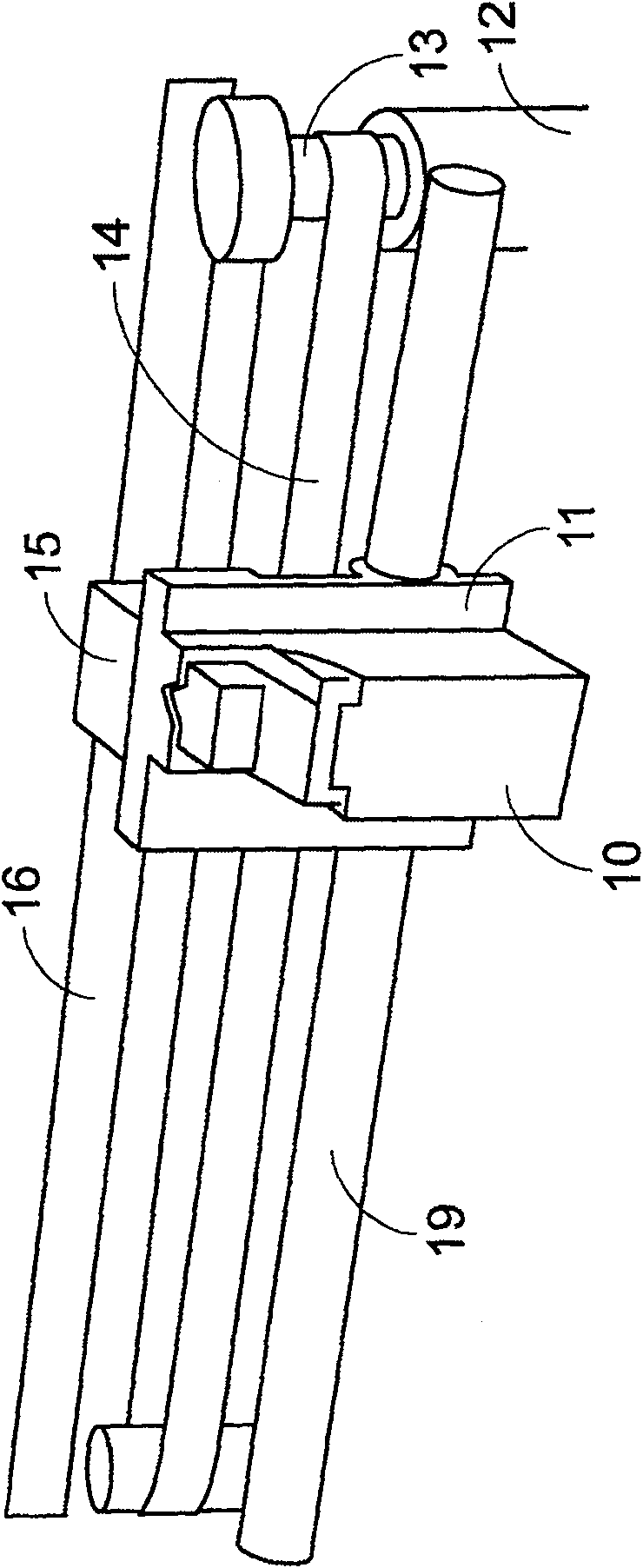
technical field [0001] The invention relates to a drive control device, in particular to a drive control device applied to a printing head and a drive transmission device of a printing device. Background technique [0002] See figure 1 , which is a schematic diagram of the internal structure of a common inkjet printer, wherein the gear 13 and the belt 14 are driven by the motor 12 to move, so that the bearing seat 11 of the inkjet head 10 can reciprocate linearly along the sliding rod 19, so that the inkjet The head 10 can go to a predetermined position to perform a printing job. In order to enable the control unit (not shown in this figure) to know the exact position of the inkjet head 10, an optical encoder 15 also carried on the bearing seat 11 will generate a position feedback signal according to the scale on the optical scale 16. The speed feedback signal is transmitted to the control unit to control the movement of the inkjet head 10 . [0003] see you again figur...

Claims


Application Information

Patent Timeline
Patent Type & Authority Patents(China)
IPC IPC(8): B41J29/38G05D3/20
Inventor 林育贤
Owner PRIMAX ELECTRONICS LTD
Learn More