Card delivery device and card receiving and distributing machine using same and card box

A technology of pushing mechanism and card, which is applied to computer parts, transmission record carriers, instruments, etc., can solve the problems of pallet displacement, tilt, horizontal support, aligning the slot of the bayonet, friction and other problems , to achieve the effect of low card output failure rate and reduced card output failure rate

Inactive Publication Date: 2010-01-27
曾蕴仪
View PDF7 Cites 0 Cited by
  • Summary
  • Abstract
  • Description
  • Claims
  • Application Information

AI Technical Summary

Problems solved by technology

Since the card outlet is a slit through which only one card can pass, the card to be pushed out must be in a horizontal state and be accurately aligned with the card outlet, otherwise the card cannot be pushed out smoothly, and a card ejection failure will occur
And the biggest reason that causes the card to be unable to ensure that it is aligned horizontally with the slit of the bayonet outlet is that the card pushing mechanism of the prior art is inaccurate and only driven by the elasticity of the spring. The spring "suspends" the card, the card can be tilted and moved, and the existing technology is to install the card pushing mechanism in the card storage box that must be moved frequently, that is, the pallet is "suspended" in the card storage box by the spring If the card storage box is moving, if there is any bump or fall during the moving process, it will easily cause the pallet to shift and tilt, or sand and dust will fly into the card storage box, which will cause friction between the card and the card storage box wall , the soft elastic force cannot support the card horizontally and align with the slit of the bayonet outlet, thus causing a card ejection failure

Method used


Image

  • Card delivery device and card receiving and distributing machine using same and card box
  • Card delivery device and card receiving and distributing machine using same and card box
  • Card delivery device and card receiving and distributing machine using same and card box

Examples


Embodiment 1

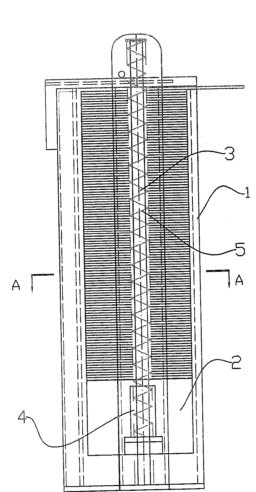
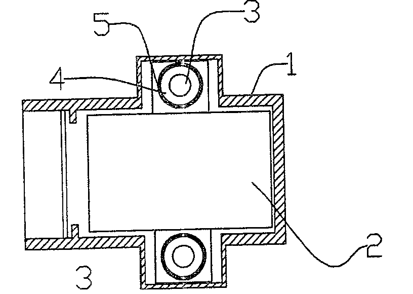
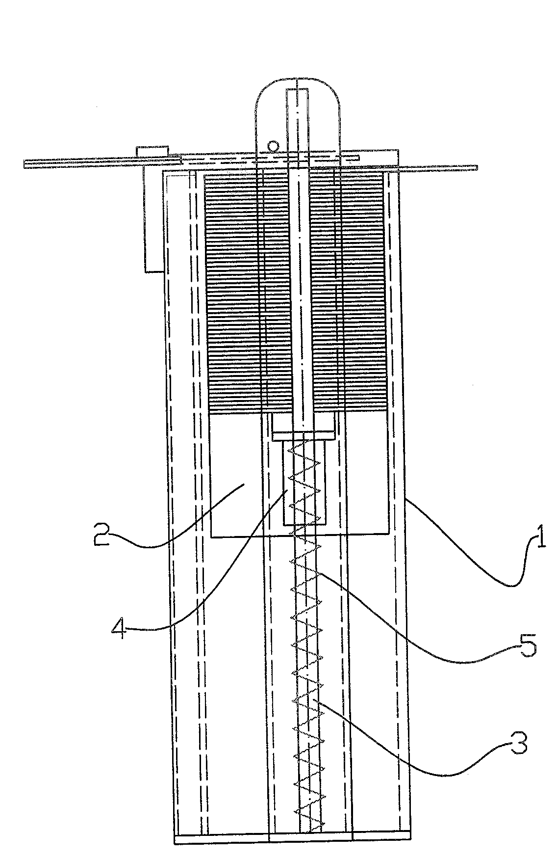
[0025] A card push mechanism, such as figure 1 , 2 The card storage box 1 is equipped with a support plate 2 that can move longitudinally, the longitudinal guide rods 3 are fixed on both sides of the card storage box, the guide sleeves 4 fixed on both sides of the support plate are set on the guide rod 3 and can slide, and the spring 5 is a tension spring. Its two ends are respectively connected with the guide sleeve 4 and the top of the card storage box 1 . The two ends of the spring 5 can also be connected to the top of the pallet 2 and the card storage box 1 respectively. Spring 5 also can be stage clip, as image 3 As shown, the two ends of the spring 5 are pressed against the bottom surface of the guide sleeve 2 and the card storage box 1 respectively. The spring 5 can also be pressed between the guide sleeve 4 and the bottom surface of the card storage box, such as Figure 4 . Guide sleeve 4 can be as Figure 10 The centers shown are through holes, which can also b...

Embodiment 2

[0027] Such as Figure 5 , 6 A longitudinal guide rod 3 is fixed on one side of the card storage box 1, and the guide sleeve 4 fixed on the supporting plate 2 is sleeved on the guide rod 3. Figure 4 Provided is extension spring 5. Certainly also can be stage clip (not giving accompanying drawing), all the other are identical with embodiment one.

Embodiment 3

[0029] A card storage box, such as image 3 , the card storage box 1 is equipped with a longitudinal guide rod 3, the guide sleeve 4 is set on the guide rod 3, the supporting plate 2 is fixed with the guide sleeve 4, and the spring 5 is connected with the guide sleeve 4 and the wall surface of the box body, which can drive the supporting plate 2 along the guide The rod moves upwards, and the spring shown in the figure is a compression spring, and of course it can also be a tension spring (such as figure 1 ). Spring 5 can also connect supporting plate 2 and box body wall, as Figure 4 .


PUM


Abstract

The utility model discloses a card pusher device, a card send-receiver machine and a card box wherein the card send-receiver machine and the card box use the card pusher device; the support plate of the card pusher device is driven by the elasticity of a spring to lengthways move along the card box; a guide sleeve is covered on a leader and can lengthways move; the guide sleeve is parallel to the card box and is connected with the support plate; the support plate is arranged on the leader by the guide sleeve; the guide sleeve matches with the leader closely in order to ensure that the guide sleeve can only lengthways slip along the leader and can not swing, therefore the support plate fixed on the guide sleeve can only horizontally move up and down in order to ensure that the card on the support plate can accurately align with the card outlet of the card send-receiver machine at a level condition and reduce the failure rates of the card box and the card send-receiver machine.

Description

technical field [0001] The invention relates to a card receiving and receiving machine used in a highway toll collection system, in particular to a card pushing mechanism for pushing stacked cards to a card outlet one by one, and a card receiving and receiving machine and a card storage box using this mechanism. Background technique [0002] Expressways or parking lots use unattended automatic card receiving and receiving machines. Passing drivers press a button, and the card issuer automatically spits out an IC card for billing. Its equipment makes the management of the toll system simple, convenient, rigorous and saves a lot of manpower and operation management costs. It is the most advanced management method of the toll system. If people go to the scene to deal with the fault, it will cause traffic jams. Therefore, the requirements for the card failure rate of the unattended card issuing machine are extremely strict. [0003] It is understood that the automatic card re...

Claims


Application Information

Patent Timeline
Patent Type & Authority Patents(China)
IPC IPC(8): G06K13/10
Inventor 曾蕴仪施永灿李忠汤兰康
Owner 曾蕴仪
Why Eureka
Try Eureka