Storage battery and insulator and battery-use container using them

A technology for batteries and electrode rods, which is applied to battery pack parts, circuits, electrical components, etc., and can solve problems such as insufficient adhesion of insulating materials

Inactive Publication Date: 2010-01-27
HONDA MOTOR CO LTD +1
View PDF13 Cites 0 Cited by
  • Summary
  • Abstract
  • Description
  • Claims
  • Application Information

AI Technical Summary

Problems solved by technology

[0025] However, covering the surface of the cover to which the insulating material is attached with a polyester resin film is disadvantageous because the polyester resin film shows insufficient adhesion to the insulating material

Method used


Image

  • Storage battery and insulator and battery-use container using them
  • Storage battery and insulator and battery-use container using them
  • Storage battery and insulator and battery-use container using them

Examples


Embodiment 1

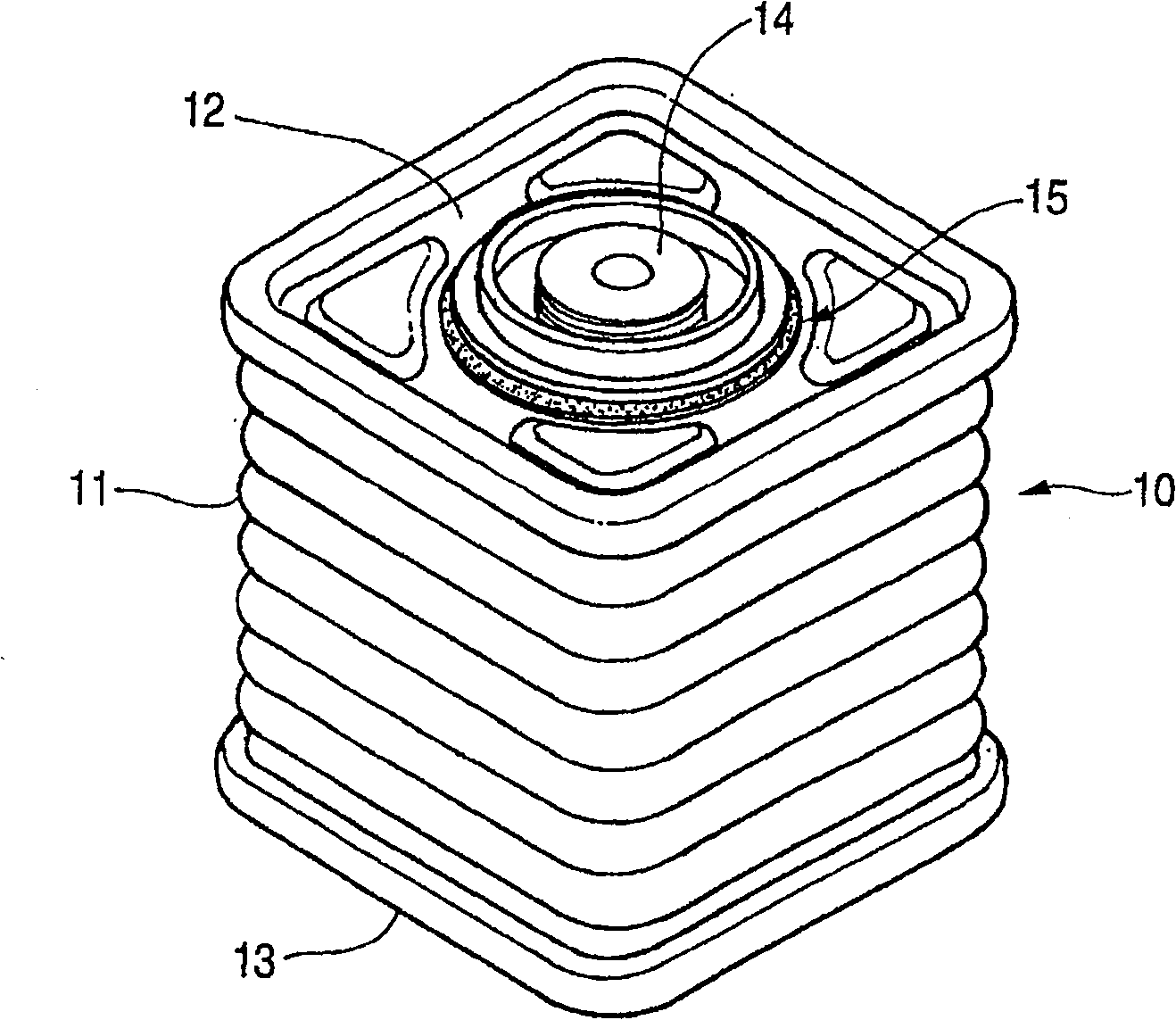
[0117] figure 1 is a perspective view of a battery according to the invention, a battery 10 is a sealed case comprising a corrugated (corrugated) barrel 11 , the upper opening of which is closed by a cover 12 and the lower opening of which is closed by a bottom cover 13 . The bottom cover 13 can be formed simultaneously with the barrel 11 by deep drawing. Reference numeral 14 denotes an electrode shaft, and reference numeral 15 denotes a ring.

[0118] Explained below Figure 9 In the cover body 12 (30), the cover body 12 (30) has a hole 16 formed in its center, and a plurality of through holes 131 (37) are formed therein surrounding the hole 16. These through holes 131 ( 37 ) are formed to enhance the fixity of the ring member 15 .

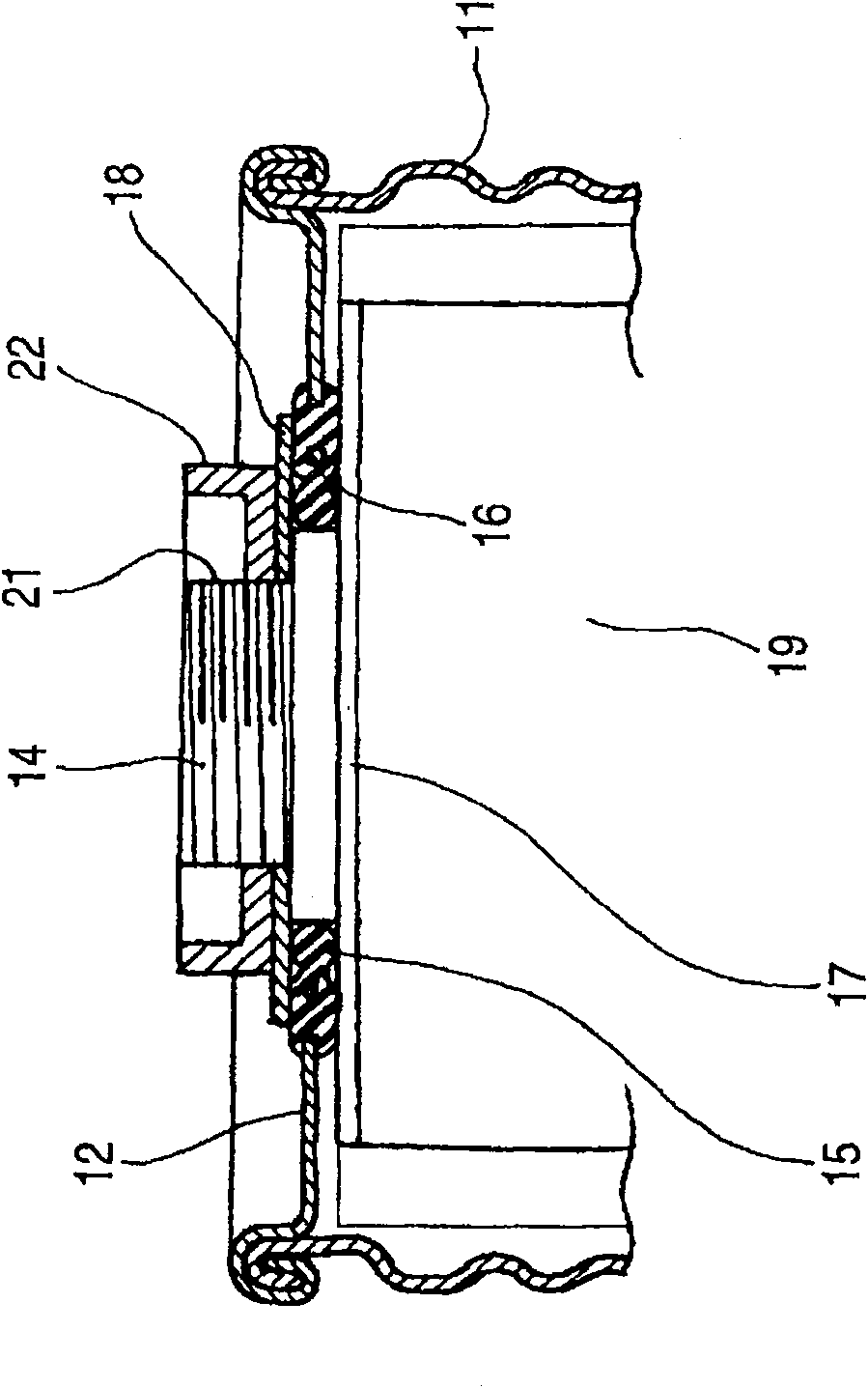
[0119] figure 2 is a sectional view of the main part of the storage battery according to the present invention, and shows a structure including a cover body 12 having a hole 16 formed therein, a ring member 15 arranged around the hole 16, a...

Embodiment 2

[0131] Another embodiment for carrying out the present invention will be described below.

[0132] Figure 5 is showing image 3 and includes a cover body 12 having a hole 16 formed therein, a ring member 15 disposed around the hole 16, arranged on one side of the cover body 12 (the lower side when viewed in the figure) The current collecting plate 17 on the top, the electrode rod 14 extending from the current collecting plate 17 and set to be able to extend out of the hole 16, and the pressing plate arranged on the other side (the upper side when viewed in the figure) of the cover body 12 18.

[0133]Also, the ring member 15 is formed of a resin sheet, and its front end is provided with a slope 28 for pressing against an O-ring 27 provided at the base of the electrode rod 14 .

[0134] In addition, the resin sheet is a hard resin having high strength but poor stretchability.

[0135] Figure 6 is showing Figure 5 In the diagram of the function, the electrode rod 14 exte...

Embodiment 3

[0138] Figure 7 is showing image 3 and includes a cover body 12 having a hole 16 formed therein, a ring member 15 arranged around the hole 16, arranged on one side of the cover body 12 (the lower side when viewed in the figure) The current collecting plate 17 on the top, the electrode rod 14 extending from the current collecting plate 17 and set to be able to extend out of the hole 16, and the pressing plate arranged on the other side (the upper side when viewed in the figure) of the cover body 12 18.

[0139] Also, the ring 15 is formed of a resin sheet, and its front end is provided with a slope 28 for pressing against a paint 29 made of a composition including a PPT-based resin provided at the base of the electrode rod 14 .

[0140] In addition, the resin sheet is also a hard resin having high strength but poor stretchability, as in the foregoing embodiments.

[0141] Figure 8 is showing Figure 7 In the diagram of the function, the electrode rod 14 extends downward ...


PUM

PropertyMeasurementUnit
thicknessaaaaaaaaaa
thicknessaaaaaaaaaa

Abstract

The present invention provides a storage battery capable of keeping a sealing feature at an electrode rod penetrating portion for an extended time. A storage battery comprising an annular member (15) provided to surround a hole (16) made in a lid (12), an electrode rod (14) extending from a collector plate (17), disposed on one side of the lid (12), and protruding through the hole (16), and a pressing plate (18) disposed on the other side of the lid (12) and holding, in collaboration with the collector plate (17), the annular member (15) between them to thereby fix the electrode rod (14) to the lid (12), wherein a collar (23) thicker than the lid (12) is provided at the base of the electrode rod (14) so that this collar (23) receives the pressing plate (18) and the annular member (15)is formed of a rubber plate thicker than the collar (23), or the annular member (15) is formed of a resin plate and an inclined surface (28) for pressing an O ring (27) set at the base of the electrode rod (14) is provided at the tip end of the resin plate.

Description

technical field [0001] The present invention relates to a technology for enhancing the sealing performance of the through hole of the electrode rod of the storage battery. [0002] The present invention also relates to an insulating material excellent in resistance to electrolyte corrosion and a battery container including the insulating material, more particularly to an insulating material made of polyethylene terephthalate resin and the insulating material A battery container attached to a cover obtained by forming an aluminum plate coated with polyester resin. Background technique [0003] With the electrification / electronicization of automobile devices, the use of rechargeable products such as secondary batteries, electrolytic capacitors and capacitors (referred to as "batteries") is increasing. [0004] The accumulator has an electrical storage element received in a sealed housing, from which electrical energy is extracted via electrodes, so that it is necessary for th...

Claims


Application Information

Patent Timeline
Patent Type & Authority Patents(China)
IPC IPC(8): H01M2/06H01M2/04H01M2/08
CPCY02E60/10
Inventor 安田范史加藤久小山茂树驹泽映祐松本康弘佐佐木秀二村上显一石井将之藤本宽黑田宽治由井义明森贺俊典弘津宗光
Owner HONDA MOTOR CO LTD
Why Eureka
Try Eureka