Abrasion-proof arrangement

A technology of wear-resistant blocks and wear-resistant parts, which is applied in the wear-resistant field, can solve the problems of large frictional resistance of the wear-resistant surface, affecting the opening and closing of the mold, and the repeated sliding of the slider is not smooth enough, so as to achieve sensitive sliding and reduce contact friction. Resistance, the effect of reducing contact frictional resistance

Inactive Publication Date: 2010-02-24
HONG FU JIN PRECISION IND (SHENZHEN) CO LTD +1
View PDF0 Cites 0 Cited by
  • Summary
  • Abstract
  • Description
  • Claims
  • Application Information

AI Technical Summary

Problems solved by technology

However, the frictional resistance of the wear-resistant surface of this wear-resistant block is still relatively large, so that the sliding block in contact with it is not smooth enough when sliding repeatedly, thereby affecting the opening and closing of the mold and affecting the use effect of the mold.

Method used


Image

  • Abrasion-proof arrangement
  • Abrasion-proof arrangement
  • Abrasion-proof arrangement

Examples


Embodiment Construction

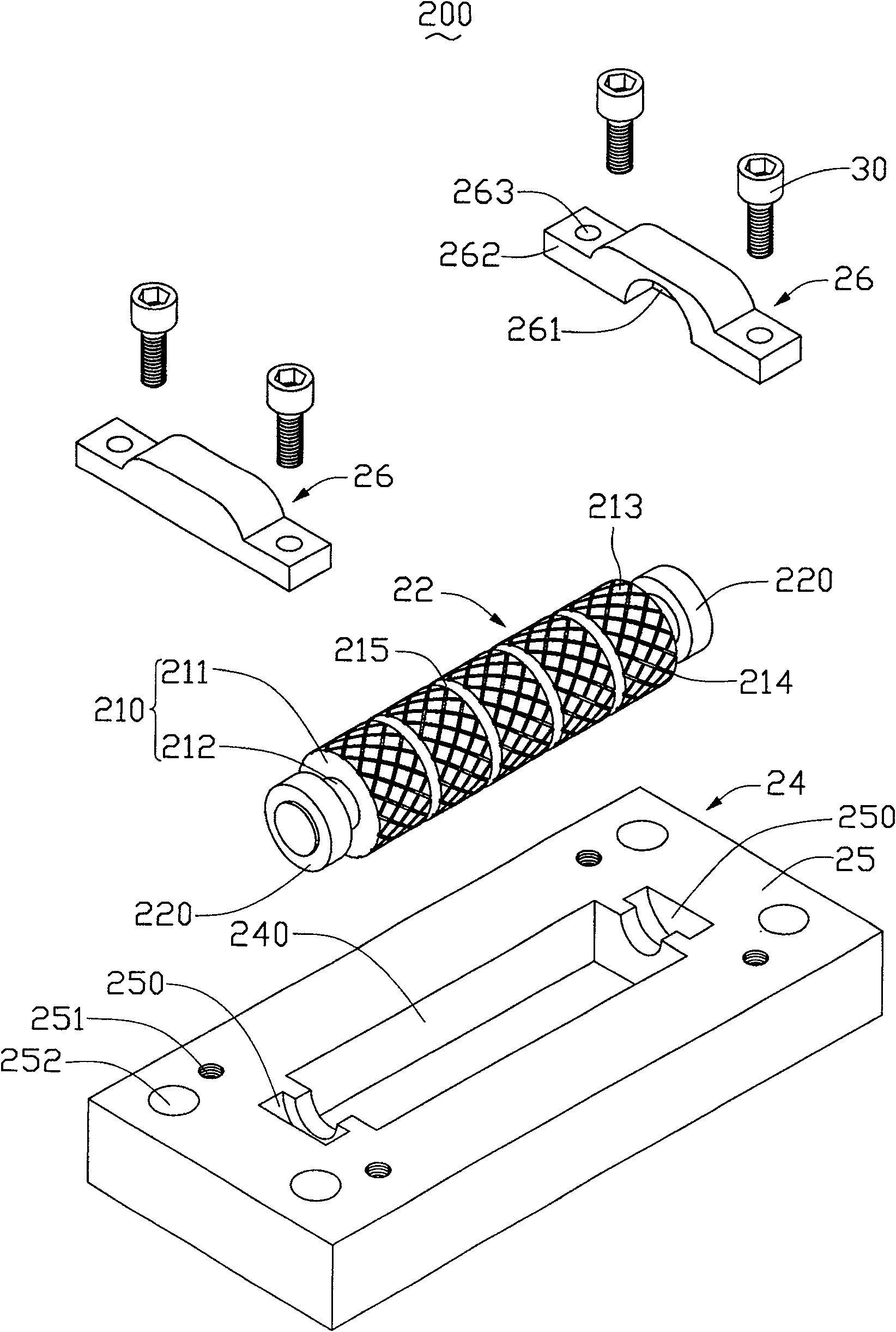
[0014] refer to image 3 and Figure 4 , the wear-resistant device 200 provided by Embodiment 1 includes a wear-resistant piece 22 , a base 24 and two fixing pieces 26 .

[0015] The wear member 22 includes a rotating portion 210 and two fixing portions 220 .

[0016] The rotating part 210 includes a wear-resistant block 211 and a rotating shaft 212 . The wear-resistant block 211 is a cylindrical structure and sleeved on the rotating shaft 212 . The rotating shaft 212 is rotatable. The inner diameter of the cylinder of the wear-resistant block 211 matches the rotating shaft 212 so as to be sleeved on the rotating shaft 212 . When the inner diameter of the cylinder of the wear block 211 is greater than the diameter of the rotating shaft 212, the wear block 211 sleeved on the rotating shaft 212 can rotate on the rotating shaft 212, and it can also be driven by the rotation of the rotating shaft 212 to rotate; when the wear block When the inner diameter of the barrel of 211 is...


PUM


Abstract

The invention relates to an anti-wear device which includes a base seat and at least an anti-wear part; the base seat is provided with at least a concave trough; the anti-wear part is arranged in thecorresponding concave trough; the anti-wear part includes a rotary part and a fixing plate; the anti-wear surface is arranged on the rotary part and is matched and rotated with the motion direction ofthe work piece contacted with the rotary part; the anti-wear surface is provided with a plurality of strip-shaped concave troughs; the fixing plate is arranged on the base seat. When the anti-wear device is contacted with the bottom of a sliding block, the contact friction resistance can be effectively reduced, enabling the sliding block to slide more sensitively and smoothly on the anti-wear surface.

Description

technical field [0001] The invention relates to a wear-resistant technology, in particular to a wear-resistant device for an injection mold. Background technique [0002] Plastic parts with complex shapes and structures are mostly manufactured by injection molding. Because of the complex structure and shape, the molds for forming such products are also relatively complicated. The removal of the products cannot be achieved by a simple mold opening, often with the help of side core pulling. Slider, before parting the mold, withdraw the slider of the side core, which is convenient for mold opening. In order to avoid wear to the mold due to the repeated sliding of the slider during the process of opening and closing the mold with the slider, usually the injection molding mold needs to be provided with a wear-resistant device such as a wear-resistant plate or a wear-resistant block at the bottom of the slider. Therefore, the wear-resistant device not only needs to have good wear...

Claims


Application Information

Patent Timeline
Patent Type & Authority Patents(China)
IPC IPC(8): B29C45/17B29C45/26
Inventor 杜健生
Owner HONG FU JIN PRECISION IND (SHENZHEN) CO LTD
Why Eureka
Try Eureka