Musical instrument package box based on limited structure of musical instrument appliance
A technology for packing boxes and musical instruments, applied in the directions of packaging, transportation and packaging, containers, etc., can solve the problems of long-term wear and damage, etc.
- Summary
- Abstract
- Description
- Claims
- Application Information
AI Technical Summary
Problems solved by technology
Method used
Image
Examples
Embodiment 1
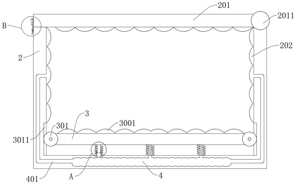
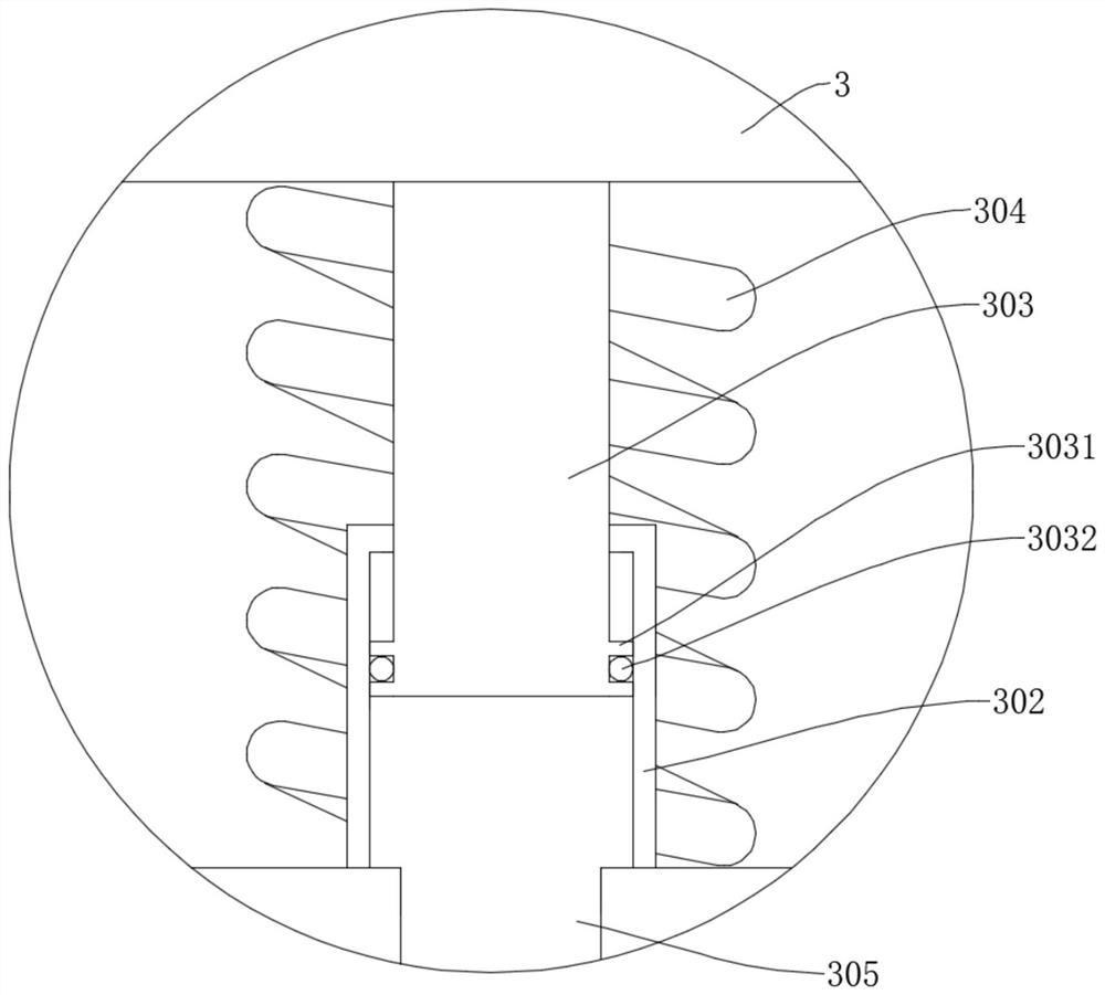
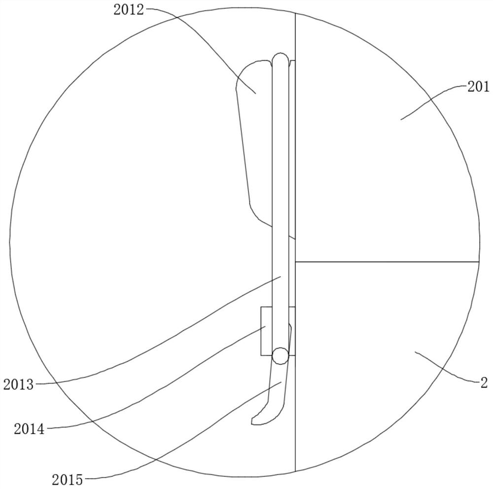
[0033] refer to figure 1 , figure 2 and Figure 4, a musical instrument packaging box with a limit structure based on musical instruments, including a first box body 1 and a second box body 2 placed in the first box body 1, a shock absorbing plate 103 is arranged in the first box body 1, and The vibration plate 103 is fixedly connected in the first box body 1 through the shock absorbing rod 104, the first air bag 202 is fixedly connected on the inner side wall of the second box body 2, and the bottom guard plate 3 is slidingly connected in the second box body 2, and the bottom The top of the guard plate 3 is fixedly connected with a second air bag 3001, the bottom of the bottom guard plate 3 is fixedly connected with an air rod 303, and the second box body 2 is fixedly connected with an air chamber 302, and the air rod 303 is slidably connected in the air chamber 302. 303 and the air chamber 302 are sleeved with a first spring 304, and the two ends of the first spring 304 r...
Embodiment 2
[0035] refer to Figure 4 , is basically the same as Embodiment 1, furthermore, the top of the first box body 1 is rotatably connected with the first box door 101 through the first rotating shaft 1011, and the side wall of the first box body 1 is rotatably connected with a strut 102, and the strut 102 is rotatably connected with moving wheels 1021, and is fixedly connected with a handle 1001 on the first box body 1. Opening the first box door 101 can place the second box body 2 in the first box body 1, and the first box body 1 is provided with Some handles 1001 and moving wheels 1021 are convenient for moving the first box body 1 .
Embodiment 3
[0037] refer to Figure 5 , Figure 6 and Figure 7 , is basically the same as Embodiment 1, furthermore, the damping rod 104 includes a rotating rod 1042 and a sleeve 1041, the rotating rod 1042 is slidably connected in the sleeve 1041, and the top of the rotating rod 1042 is fixedly connected with a cylindrical block 1043, and the cylindrical block 1043 is fixedly connected with a rotary block 1044, the first box body 1 is provided with a rotary groove matching with the rotary block 1044, the side wall of the rotary rod 1042 is fixedly connected with a spiral guide block 1047, and the sleeve 1041 is provided with a spiral groove 1046 , the spiral guide block 1047 is slidably connected in the spiral groove 1046, the second spring 1045 is arranged in the sleeve 1041, and the two ends of the second spring 1045 respectively resist the rotating rod 1042 and the first box body 1, and the rotating rod 1042 is fixedly connected The spiral guide block 1047 makes the rotating rod 10...
PUM
 Abstract
Description
Claims
Application Information
 - R&D
- Intellectual Property
- Life Sciences
- Materials
- Tech Scout
- Unparalleled Data Quality
- Higher Quality Content
- 60% Fewer Hallucinations
Browse by: Latest US Patents, China's latest patents, Technical Efficacy Thesaurus, Application Domain, Technology Topic, Popular Technical Reports.
© 2025 PatSnap. All rights reserved.Legal|Privacy policy|Modern Slavery Act Transparency Statement|Sitemap|About US| Contact US: help@patsnap.com


