Gravity sensor

A technology of gravity sensor and weight-reducing groove, applied in the field of sensors, can solve the problems of complex structure, low service life, insensitive response, etc., and achieve the effects of simple overall structure, guaranteeing elasticity, and improving detection accuracy and sensitivity

Inactive Publication Date: 2017-12-15
CHONGQING YUANWANG LOGISTIC
View PDF14 Cites 0 Cited by
  • Summary
  • Abstract
  • Description
  • Claims
  • Application Information

AI Technical Summary

Problems solved by technology

[0003] Aiming at the deficiencies in the prior art, the present invention provides a gravity sensor, which solves the problems of low service life, insensitive response and complicated structure of the existing gravity sensor

Method used


Image

  • Gravity sensor
  • Gravity sensor
  • Gravity sensor

Examples


Embodiment Construction

[0013] The present invention will be further described below in conjunction with the accompanying drawings.

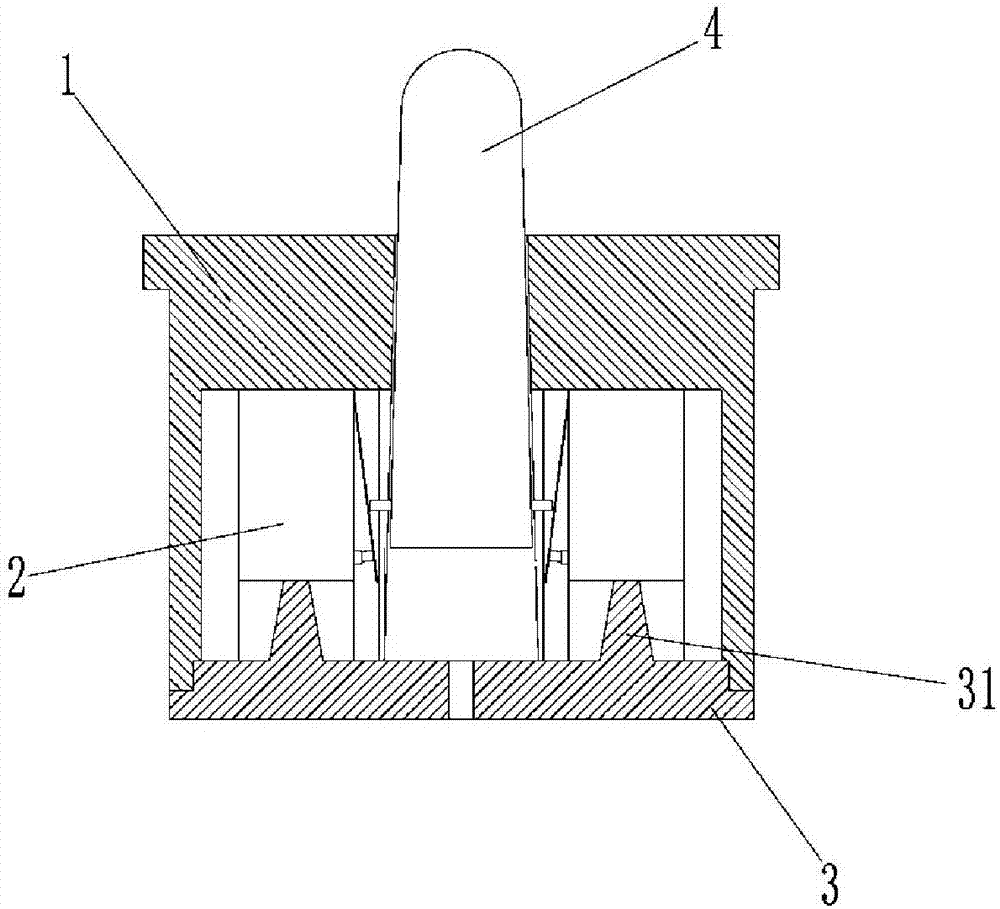
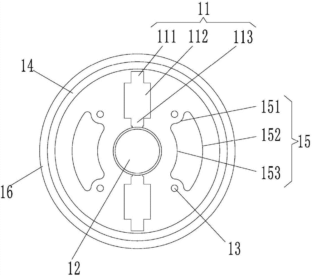
[0014] Such as Figure 1 ~ Figure 2 As shown, a gravity sensor according to the present invention includes a housing 1 and a bottom cover 3 matched with the housing 1. A symmetrical installation groove 11 is opened on the upper surface of the housing 1. The installation groove 11 It includes cable trough 111, switch receiving trough 112 and guide chute 113 connected in sequence, and the width of switch receiving trough 112 is greater than the width of cable trough 111 and guide chute 113, and a rounded structure is provided on the transition edge to avoid Disadvantages caused by processing burrs. A micro switch 2 is placed in the switch receiving groove 112, and the shrapnel of the micro switch 2 obliquely passes through the guide chute 113, and the connecting terminal of the micro switch 2 is located in the cable groove 111; There are two symmetrical protruding post...


PUM


Abstract

The invention provides a gravity sensor, and the sensor comprises a housing. The upper surface of the housing is provided with symmetric installation grooves, and each installation groove comprises a cable duct, a switch accommodation groove and a guide chute, wherein the cable duct, the switch accommodation groove and the guide chute are sequentially communicated, a microswitch is disposed in the switch accommodation groove, the elastic piece of the microswitch passes through the guide chute in an inclined manner, and a wiring end of the microswitch is located in the cable duct. The central part of the housing is provided with a through taper hole, and the interior of the taper hole is provided with a touch rod which can slide. Moreover, the periphery of the touch rod is provided with contacts in sliding fit with the guide chutes. The touch rod is pressed to move upwards, so as to enable the switch of each microswitch to be driven by deformation of the elastic piece and then output an electric signal through a signal line. The gravity sensor is simple and compact in structure, and the housing is provided with the cable ducts, the switch accommodation grooves and the guide chutes. Moreover, the microswitches are vertically installed, and the elastic piece does not deform if withstanding no force, and can guarantee the elastic force, thereby effectively avoiding the errors, and improving the detection precision and sensitivity of the sensor.

Description

technical field [0001] The invention relates to the technical field of sensors, in particular to a gravity sensor. Background technique [0002] The trigger rod and the micro switch in the existing gravity sensor are vertically arranged, the trigger rod is directly stressed on the shrapnel, and the shrapnel bears a large pressure. Long-term use is likely to cause deformation of the shrapnel, which reduces the sensitivity of the entire gravity sensor and affects the use. , and the vertical arrangement of the touch lever and the micro switch makes the stroke of the touch lever short, resulting in a low service life of the gravity sensor, insensitive response and complicated structure. Contents of the invention [0003] Aiming at the deficiencies in the prior art, the present invention provides a gravity sensor, which solves the problems of low service life, insensitive response and complex structure of the existing gravity sensor. [0004] In order to achieve the above obje...

Claims


Application Information

Patent Timeline
Patent Type & Authority Applications(China)
IPC IPC(8): G01G3/08G01G23/37
CPCG01G3/08G01G23/3728
Inventor 王茂吴强闫川海
Owner CHONGQING YUANWANG LOGISTIC
Why Eureka
Try Eureka