Supercharge Your Innovation With Domain-Expert AI Agents!

Peg for stringed instrument

一种卷线装置、弦乐器的技术,应用在弦乐器、乐器、仪器等方向,能够解决卷取轴旋转摩擦阻力变大、部件磨损等问题,达到防止接触、防止迅速磨损的效果

Inactive Publication Date: 2010-02-24
GOTOH GUT
View PDF5 Cites 0 Cited by
  • Summary
  • Abstract
  • Description
  • Claims
  • Application Information

AI Technical Summary

Problems solved by technology

However, if the take-up shaft is arranged in contact with the inner wall of the guide bush as described above, the rotational frictional resistance of the take-up shaft becomes large, so that the worm wheel cannot be rotated by the tension of the string, and the backlash becomes a play for the rotation of the worm wheel. gap
In turn, unnatural forces act on the tooth surfaces where the worm wheel and worm come into contact, causing rapid wear of these components

Method used


Image

  • Peg for stringed instrument
  • Peg for stringed instrument
  • Peg for stringed instrument

Examples


no. 1 approach

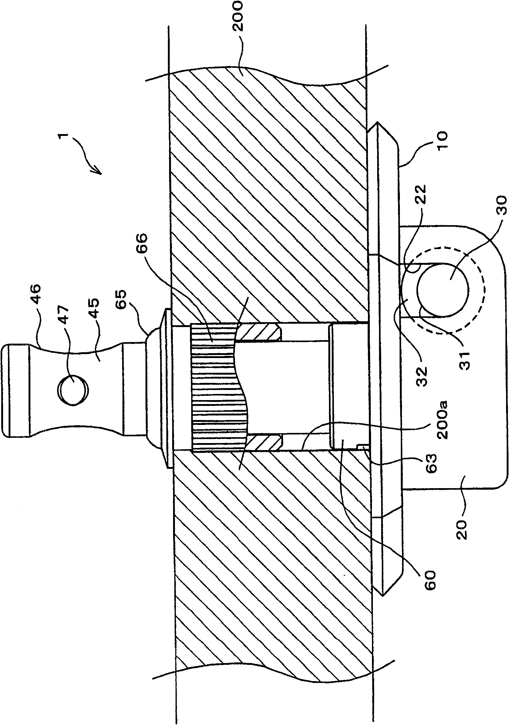
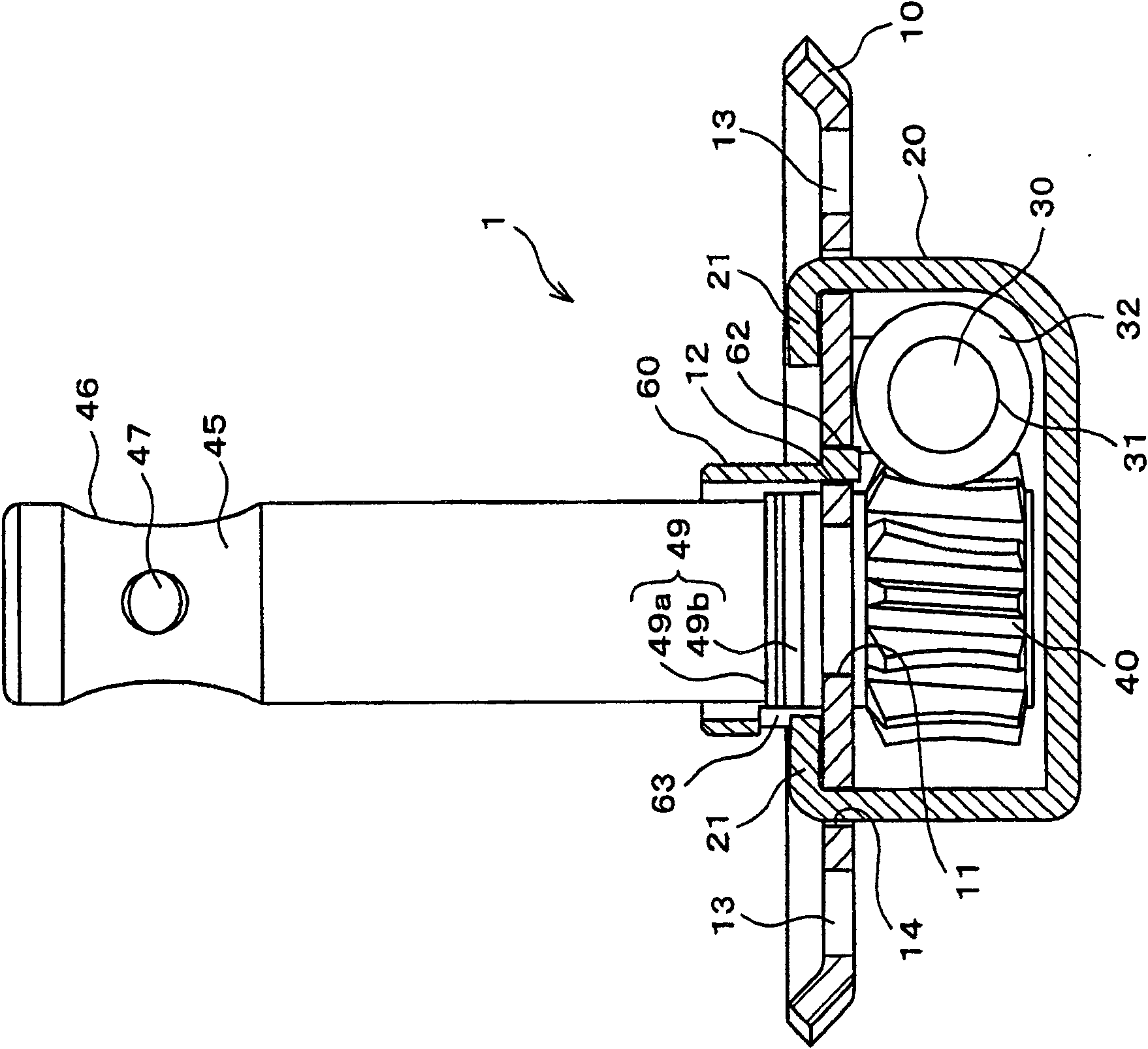
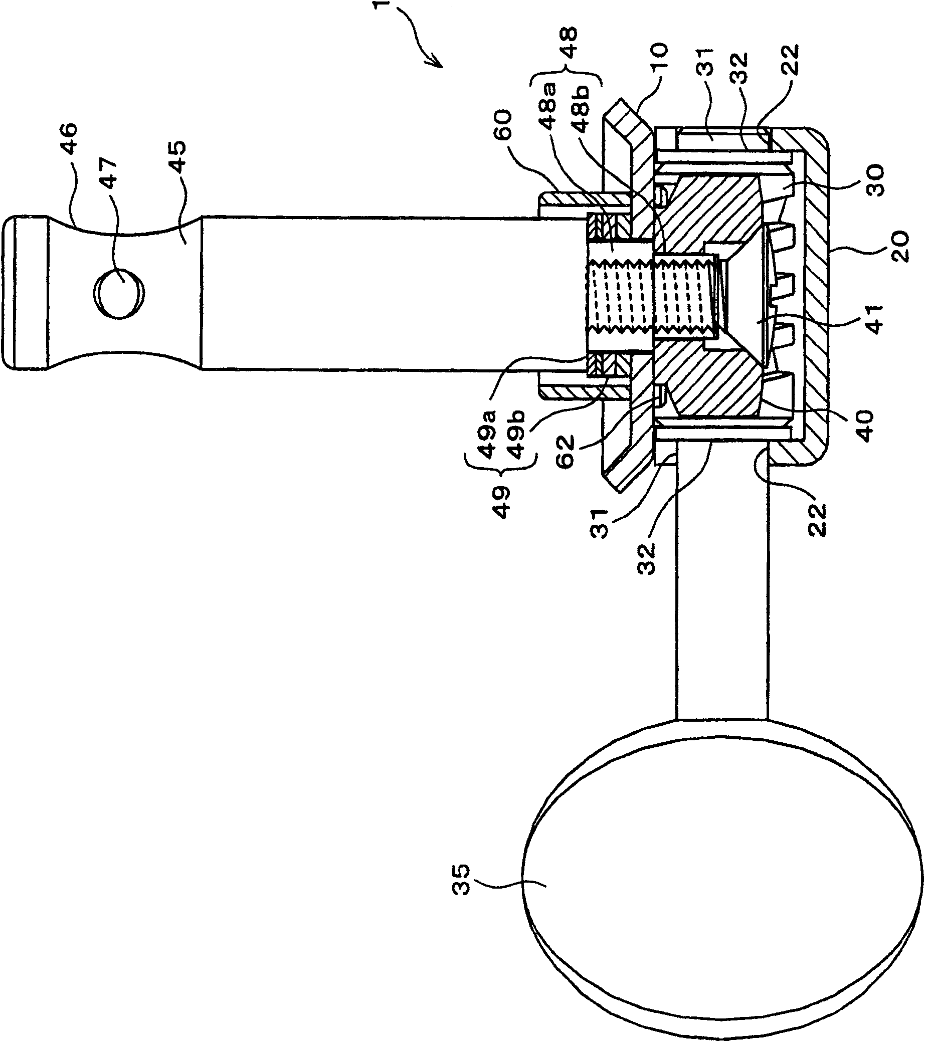
[0026] refer to Figure 1 ~ Figure 5D A first embodiment of the present invention will be described. Figure 1 ~ Figure 3 Showing the schematic structure of the wire winding device 1 according to the first embodiment of the present invention, figure 1 It is a side view of a state in which the cord winding device 1 is mounted on the head 200 of a stringed instrument viewed from the side of the head 200, figure 2 is its cross-sectional view, image 3 With figure 2 Orthogonal cutaway view. First, the outline of the overall configuration of the wire winding device 1 will be described. Reference numeral 10 in the figure is the main body of the cord winding device 1, and reference numeral 20 is the cover body. A worm 30 is rotatably supported between the cover 20 and the main body 10 . On the worm 30, a knob 35 for rotating it is installed (refer to image 3 ). In addition, a worm wheel 40 meshes with the worm 30 . A take-up shaft 45 penetrates through the hole 200 a of ...

no. 2 approach

[0038] refer to Figure 6 ~ Figure 10C A second embodiment of the present invention will be described. The second embodiment is different from the first embodiment in that only the main body of the cord winding device constitutes the bearing of the worm without using a cover. Therefore, in the following description, the same reference numerals are attached to the same components as those of the first embodiment, and description thereof will be omitted.

[0039] Reference numeral 70 in the figure represents the main body of the winding device 2, Figure 10A ~ Figure 10C Its detailed structure is shown in . The main body 10 is formed by press-forming a metal plate such as a steel plate, and has a support hole 71 formed in its central portion, and the lower end portion of the winding shaft 45 is rotatably supported by the support hole 71 . Around the support hole 71, a plurality of (three in this embodiment) insertion holes 72 are formed at equal intervals in the circumferenti...


PUM


Abstract

A peg for a stringed instrument having a head and a hole formed in the head includes: a main body which is mounted to the head; a worm gear rotatably provided to the main body and having a knob on anend portion thereof; a worm wheel rotatably supported by the main body and engaging with the worm gear; a winding shaft having an axis, the winding shaft connected to the worm wheel and inserted intothe hole of the head in the condition that the main body is mounted to the head; and a ring-shaped guide member penetrated by the winding shaft and fitted into the hole of the head. The guide member is inserted to the main body along the axis of the winding shaft so as to be secured to the main body.

Description

technical field [0001] The present invention relates to a string winding device for a stringed instrument such as a guitar, and particularly relates to a technique for aligning the center of a winding shaft with the center of a hole in a head. Background technique [0002] A stringed instrument such as a guitar is provided with a winding device for adjusting the strings. Winding device such as Figure 11 As shown, there are: a main body 110, a worm 120 rotatably supported on the main body 110, a knob 130 fixed to one end of the worm 120, a take-up shaft 140 rotatably supported on the main body 110, A worm wheel 150 is attached to the end of the take-up shaft 140 and meshes with the worm 120 . [0003] Such a wire winding device 100 is installed on the head 200 of the stringed instrument as follows, that is, the winding shaft 140 penetrates the hole 200a formed on the head 200 of the stringed instrument and the winding surface 141 of the winding shaft 140 protrudes from the ...

Claims


Application Information

Patent Timeline
Patent Type & Authority Patents(China)
IPC IPC(8): G10D3/14
CPCG10D3/14
Inventor 后藤孝夫
Owner GOTOH GUT
Features
  • R&D
  • Intellectual Property
  • Life Sciences
  • Materials
  • Tech Scout
  • Unparalleled Data Quality
  • Higher Quality Content
  • 60% Fewer Hallucinations
Learn More