Robot

A technology for a robot and an arm, applied in the field of robots, can solve problems such as the increase of the rotating joint part 110, the twisting of the wiring cable, and the easy occurrence of disconnection, and achieve the effects of being difficult to twist, preventing disconnection, and not easy to disconnect.

Active Publication Date: 2011-01-26
SANKYO SEIKI MFG CO LTD
View PDF0 Cites 0 Cited by
  • Summary
  • Abstract
  • Description
  • Claims
  • Application Information

AI Technical Summary

Problems solved by technology

[0004] As described above, there is no problem when only air is supplied to the two manipulators 102 and 103, but for example, when it is desired to install a sensor at the front end of the manipulator, it is difficult to stretch the wiring cable to the front end of the manipulator, and even if it can be stretched For the wiring cables, if the upper manipulator 102 and the lower manipulator 103 are rotated at a relatively large angle, the wiring cables may be twisted, and there are problems such as easy disconnection.
[0005] In addition, when it is desired to further supply a plurality of air pipes to the front end of the manipulator, there is a problem that the conventional rotary joint part 110 using the rotary air joint structure 111 becomes larger and more complicated.

Method used


Image

  • Robot
  • Robot
  • Robot

Examples


Embodiment Construction

[0040] The best mode for carrying out the present invention will be described below with reference to the drawings. In addition, the robot of this invention is not limited to the following description and drawing in the range which has the technical characteristic. In addition, the "manipulator control system line" refers to the air pipe for the manipulator of the robot to suck in air to perform the workpiece gripping operation, the wiring cable for driving the chuck (Japanese: チヤツク) mechanism, and the signal for the sensor for confirming the suction operation. wires and other wiring cables. In addition, the manipulator control system wire is made of a flexible material (polyethylene, etc.) that has elasticity that does not interfere with joint motion.

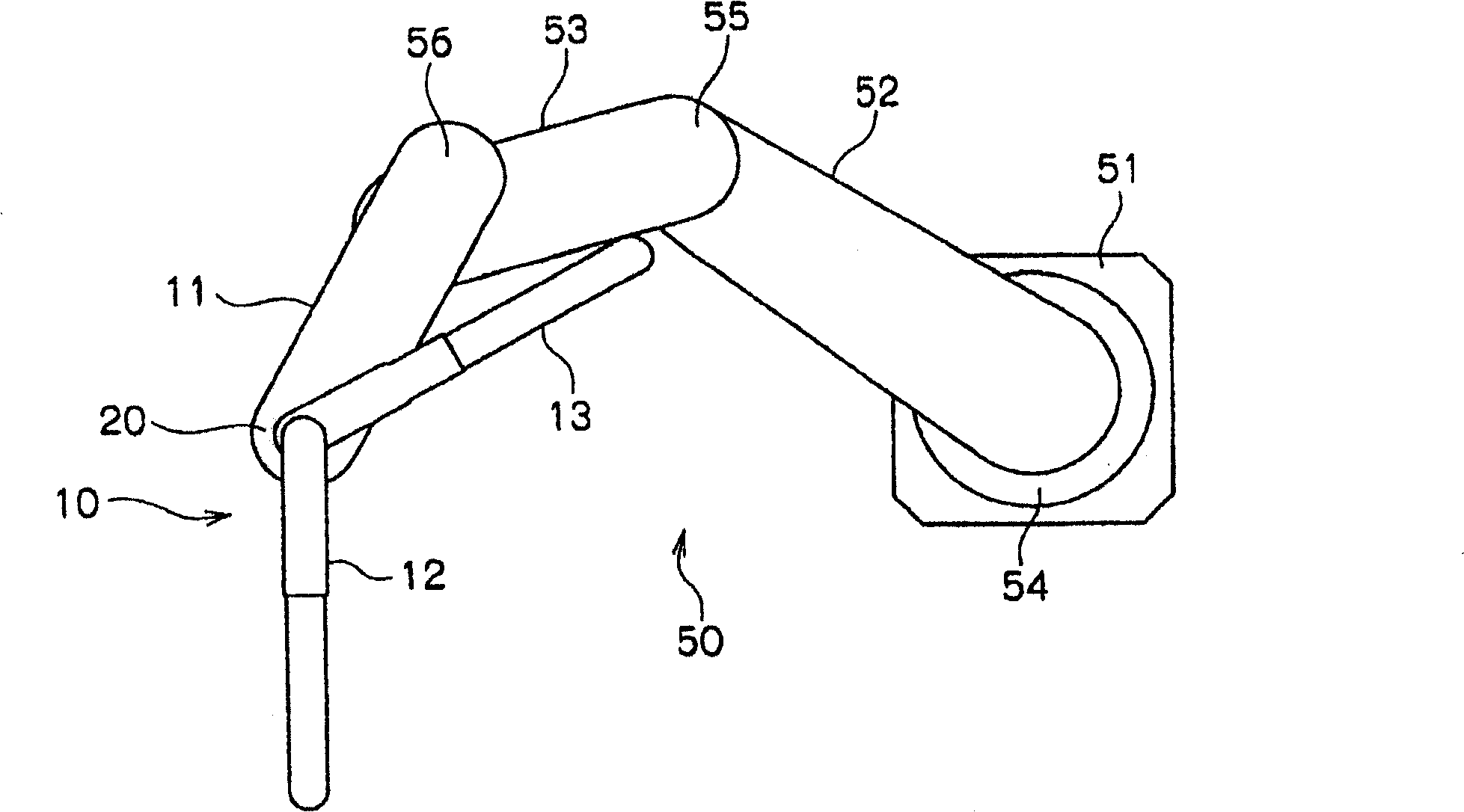
[0041] figure 1 It is a plan view showing an example of the robot of the present invention. figure 1 The shown robot 50 includes a revolving joint structure 10 with a windpipe and a cable handling structure as a manipulat...


PUM


Abstract

The invention provides a robot which can easily supply manipulator control system line for two manipulators which rotates independently and can rotate the same in larger relative degree. The robot includes manipulating arms 11, rotating joint sections 20 disposed at one end of the manipulating arms 11, a first and a second manipulators 12, 13 which lap over in two stages and are connected to the rotating joint sections 20 and respectively and independently rotate about the same rotating imaginary axis, wherein the rotating joint sections 20 includes a first connection member 14 having a hollow section 23 for leading manipulator control system lines 21, 22 to the first manipulator 12, and a gap section 24 formed by cutting part of cylinder with leaving definite length arc 29, and which is connected to the first manipulator 12 thereby rotating the same; a second connection member, disposed at the outside of the first connection member 14, and which is connected to the second manipulator13 thereby rotating the same; an annular member 26 freely rotatablely disposed between the first connection member 14 and the second connection member 15 and having a guiding member 25 for leading the manipulator control system line 22 to the second manipulator 13 via the hollow section 23 of the first connection member 14 and the gap section 24, and the manipulator control system line 22 is heldin a frame in a configuration with relaxation rate allowably following the rotation of the guiding member 25.

Description

technical field [0001] The present invention relates to a robot, in particular to a robot capable of easily supplying a manipulator control system line to two manipulators which rotate independently, and which can rotate the two manipulators at a relatively large relative angle. Background technique [0002] Image 6 It is an example of a conventional robot 100 in which two manipulators 102 and 103 are provided on a rotary joint 110 at the front end of the arm, and is a partially enlarged view showing an example of a robot having a trachea as a manipulator control system line, for example. exist Image 6 Among them, a rotary joint 110 is provided at the front end of the machine arm 101, and on the rotary joint 110, two manipulators composed of an upper manipulator 102 and a lower manipulator 103 are arranged in an overlapping manner. The two manipulators 102, 103 have the same virtual rotation axis A, the upper manipulator 102 is connected to the pulley 104 of the rotating j...

Claims


Application Information

Patent Timeline
Patent Type & Authority Patents(China)
IPC IPC(8): B25J9/06B25J13/00B25J17/00B25J18/00B25J19/00
CPCB25J9/1612B25J15/00B25J17/00B25J18/04
Inventor 北原康行改野重幸
Owner SANKYO SEIKI MFG CO LTD
Why Eureka
Try Eureka