

Steel strand retractor
A steel strand and tractor technology, applied in the field of construction tools, can solve the problem that the steel strand is difficult to pass through the corrugated pipe quickly, and achieve the effect of increasing the construction speed
- Summary
- Abstract
- Description
- Claims
- Application Information
AI Technical Summary
Problems solved by technology
Method used
Image

Examples
Embodiment Construction
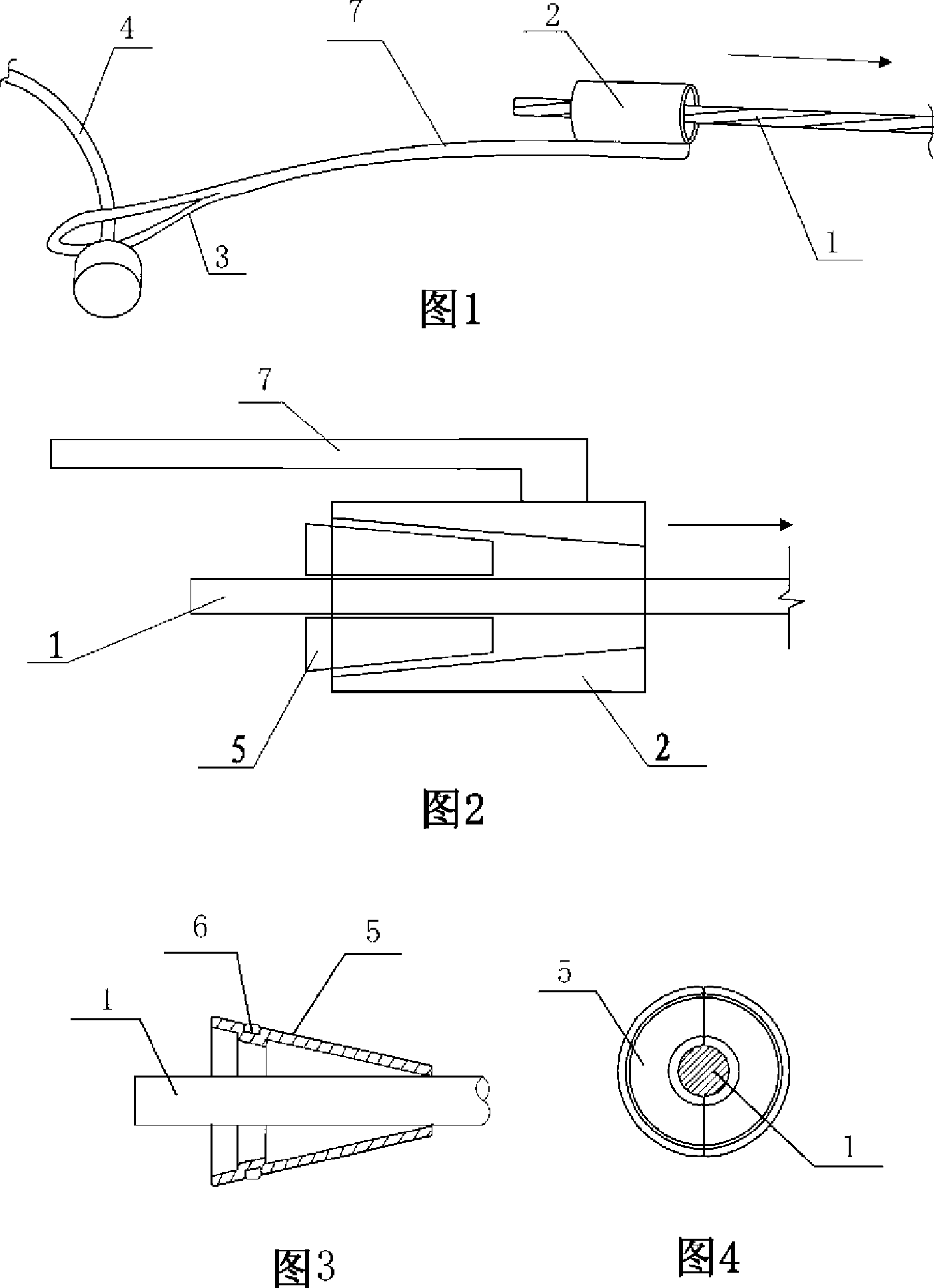
[0020] Referring to Figures 1-4 for the embodiment, this steel strand puller includes an anchoring body and a pull ring connecting the steel strands. The anchoring body is a cylinder 2 with a conical shape inside and the small head of the cone facing the pulling direction. Two wedge-shaped clips 5 for clamping the pulling tendons are installed inside the cylinder body. The outer wall of the clips has stirrup grooves, and the clips are hooped together by stirrups 6 . The inner wall of the clip is hooped on the outer periphery of the pulling rib 1, and the pulling rib extends to the outside of the cylinder along the pulling direction (direction of the arrow), and a pulling rib 7 is fixedly connected to the outer wall of the cylinder, and the pulling rib extends in the opposite direction of the pulling , the end of the tension tendon is in the shape of a pull ring, and the pull ring 3 is connected with the drawn steel strand 4 in a loop. The pulling tendons 1 above can be steel w...
PUM
 Abstract
Description
Claims
Application Information