

Method of making wall block
- Summary
- Abstract
- Description
- Claims
- Application Information
AI Technical Summary
Benefits of technology
Problems solved by technology
Method used
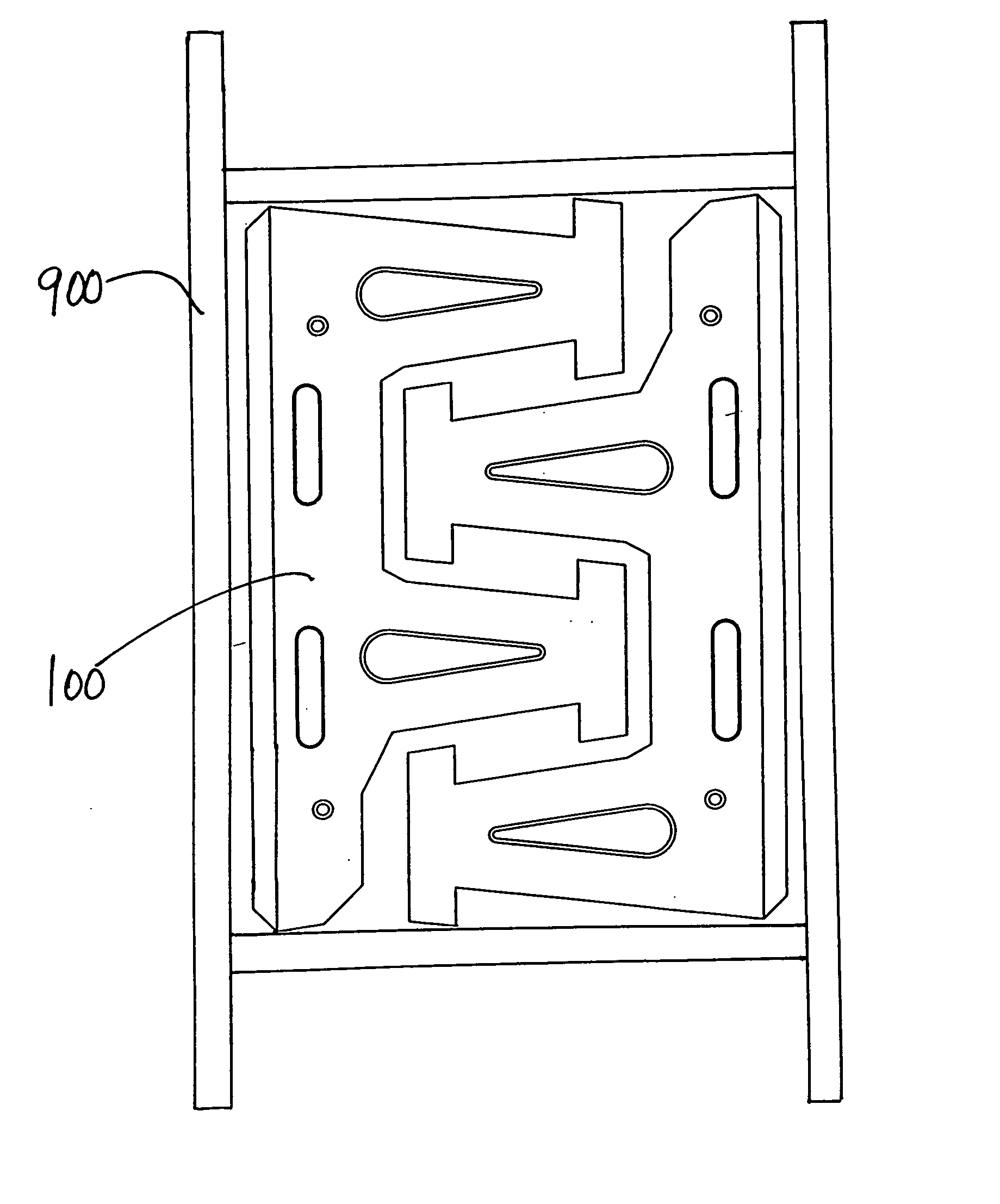
Image

Examples
Embodiment Construction
[0042] In this application, “upper” and “lower” refer to the placement of the block in a retaining wall. The lower surface faces down, that is, it is placed such that it faces the ground. In forming a retaining wall, one row of blocks is laid down, forming a course. A second course is laid on top of this by positioning the lower surface of one block on the upper surface of another block.
[0043] The blocks of this invention may be made of a rugged, weather resistant material, such as concrete, especially if the wall is constructed outdoors. Other suitable materials include plastic, reinforced fibers, and any other materials suitable for use in molding wall blocks. The surface of the blocks may be smooth or may have a roughened appearance, such as that of natural stone. The blocks are formed in a mold and various textures can be formed on the surface, as is known in the art.
[0044] Several embodiments are illustrated in the figures below. In one embodiment, this invention is a block c...
PUM
| Property | Measurement | Unit |
|---|---|---|
| Length | aaaaa | aaaaa |
| Thickness | aaaaa | aaaaa |
| Distance | aaaaa | aaaaa |
Abstract
Description
Claims
Application Information