Break tripping device

A circuit breaker tripping and tripping device technology, applied in the direction of protection switch operation/release mechanism, etc., can solve the problems of high cost, poor interchangeability, increased magnetic field, etc., and achieve the effect of low cost and simple structure improvement

Active Publication Date: 2007-07-25
JIANGSU DAQO KFINE ELECTRIC
View PDF1 Cites 25 Cited by
  • Summary
  • Abstract
  • Description
  • Claims
  • Application Information

AI Technical Summary

Problems solved by technology

[0005] The problem with the above-mentioned existing circuit breaker tripping mechanism is that it can only play a protective role when the short-circuit current is relatively large.
Although the above improvements have improved the thermal sensitivity of the tripping mechanism, and its tortuous structure has also played a role in increasing the magnetic field to a certain extent, but the parts and high-current products cannot be used in common, the interchangeability is poor, and the cost is high

Method used


Image

  • Break tripping device
  • Break tripping device

Examples


Embodiment 1

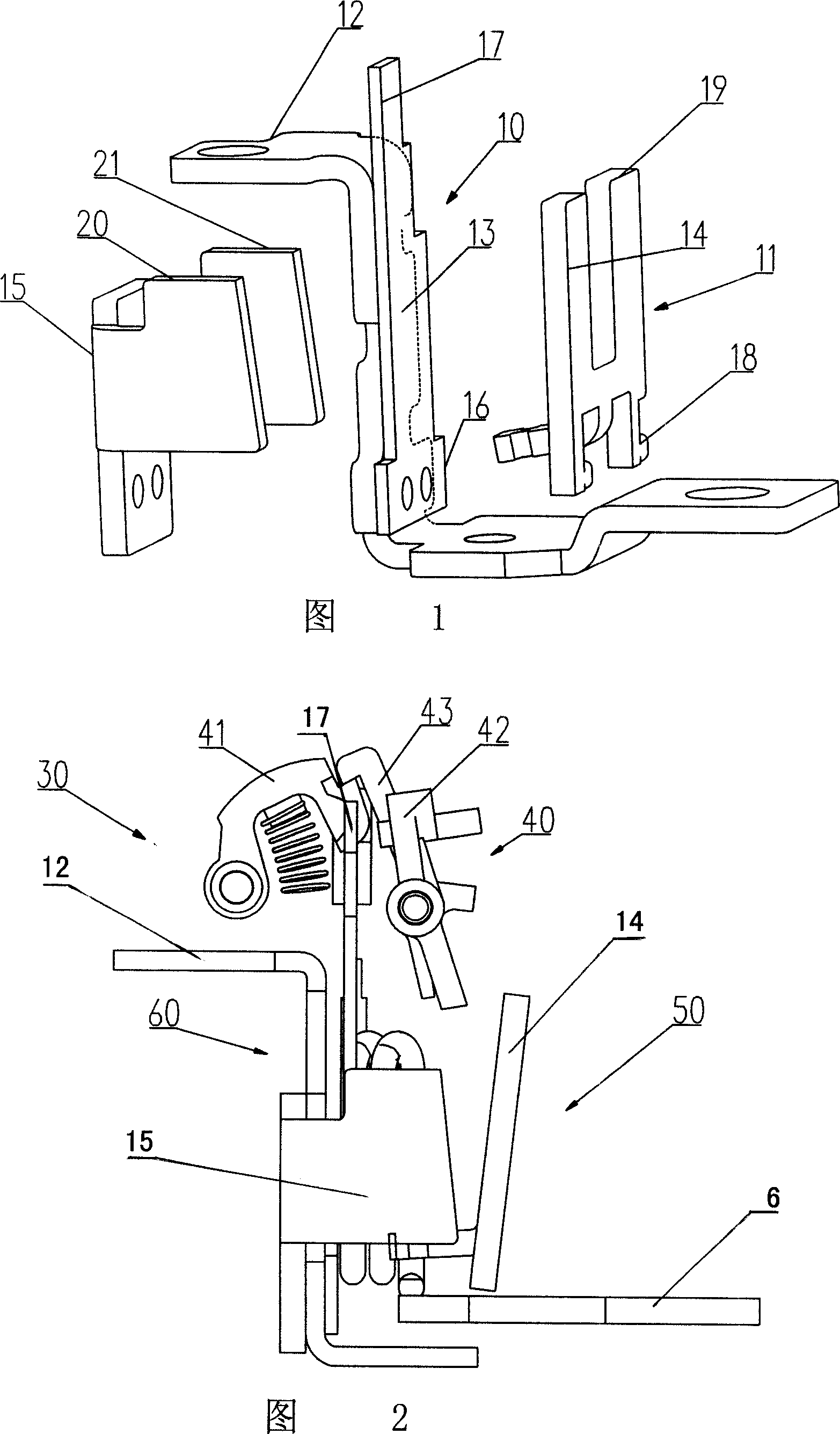
[0015] As shown in FIG. 2 , the circuit breaker tripping release 30 of this embodiment is mainly composed of an action triggering part 40 of an actuator, a thermal tripping mechanism 60 and a magnetic tripping mechanism 50 . Wherein, the action trigger part 40 of the actuator is mainly composed of a lock 41 and a draw bar 42 . One end of the buckle 41 and the middle part of the drawbar 42 are respectively hinged on the frame of the release, and the upper arm 43 of the drawbar 42 hooks the hanging end of the buckle 41 . The middle part of the buckle 41 leans against the spring and has a tendency to move upward.

[0016] During work, when an overcurrent passes through the thermal trip mechanism 60, the free end (upper end) of the bimetal strip 17 bends, pushing the upper arm 43 of the draw bar 42 to rotate clockwise, disengaging the lock 41, and then driving the actuator to act and Disconnect the circuit breaker; when a short-circuit current passes through the magnetic trip mec...


PUM


Abstract

The trip is mainly composed of part for triggering action in the actuating mechanism, and the tripping mechanism. One end of the heating unit in the tripping mechanism is as the end for inputting current; and the other end is connected to the fixed end of the bimetallic strip electrically. The free end of the bimetallic strip is near to the drawbar. U type magnetic yoke is installed near to the heating unit. Hinged one end of armature is installed related to the extension arm of the U type magnetic yoke. The free end of the armature is near to the drawbar. Winding is enwound on at least one extension arm of the magnetic yoke; When short circuit current passes through the winding, the magnetic yoke generates magnetic field intensity direct proportional to number of turns of winding. Thus, even if small current passes through the winding, magnetic field enough to attract armature can be generated. Improving structure simply, the invention overcomes problem existed in current technique.

Description

technical field [0001] The invention relates to a circuit breaker tripping release, in particular to a structural improvement of a circuit breaker tripping release, belonging to the technical field of power supply control facilities. Background technique [0002] The function of the circuit breaker is to provide time-delay protection for long-term overcurrent and protection for instantaneous large current caused by short circuit. Its protection is usually realized by means of a thermal-magnetic trip mechanism, so it includes a thermal trip part and a magnetic trip part. The typical structure is shown in Figure 1. [0003] The thermal trip part 10 in the trip mechanism includes a heating element 12 and a bimetal strip 13, and one end 16 of the bimetal strip is connected with the heating element. The bimetal sheet 13 is composed of two metal sheets with different expansion coefficients, and is close to and substantially parallel to a part of the heat element 12 . When an ove...

Claims


Application Information

Patent Timeline
Patent Type & Authority Applications(China)
IPC IPC(8): H01H71/40H01H71/16
Inventor 徐硕业马丽萍张海燕
Owner JIANGSU DAQO KFINE ELECTRIC
Why Eureka
Try Eureka