Induction code switch

A technology of coding switches and inductive switches, which is applied in the field of switches, can solve problems such as the influence of shell strength, influence, and poor sealing performance of electrical equipment, and achieve the effect of maintaining integrity

Active Publication Date: 2010-05-12
SHENZHEN TOPBAND CO LTD
View PDF1 Cites 10 Cited by
  • Summary
  • Abstract
  • Description
  • Claims
  • Application Information

AI Technical Summary

Problems solved by technology

[0003] Disadvantages of using mechanical coding switches: due to the need to open holes in the electrical equipment, the integrity of the electrical equipment shell is destroyed, and it will also affect the strength of the shell, and have a negative impact on the sealing performance of the electrical equipment. As a result, the requirements for waterproof, moisture-proof and leakage prevention cannot be met

Method used


Image

  • Induction code switch
  • Induction code switch
  • Induction code switch

Examples


Embodiment Construction

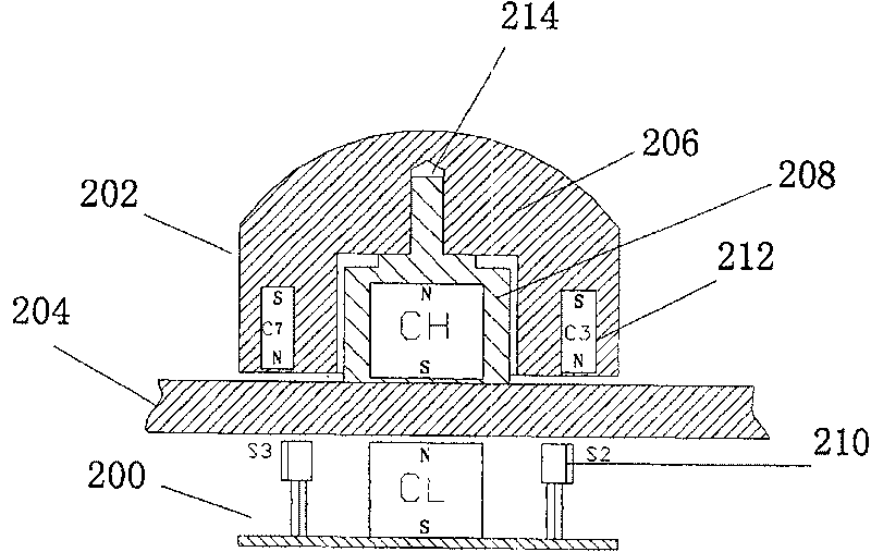
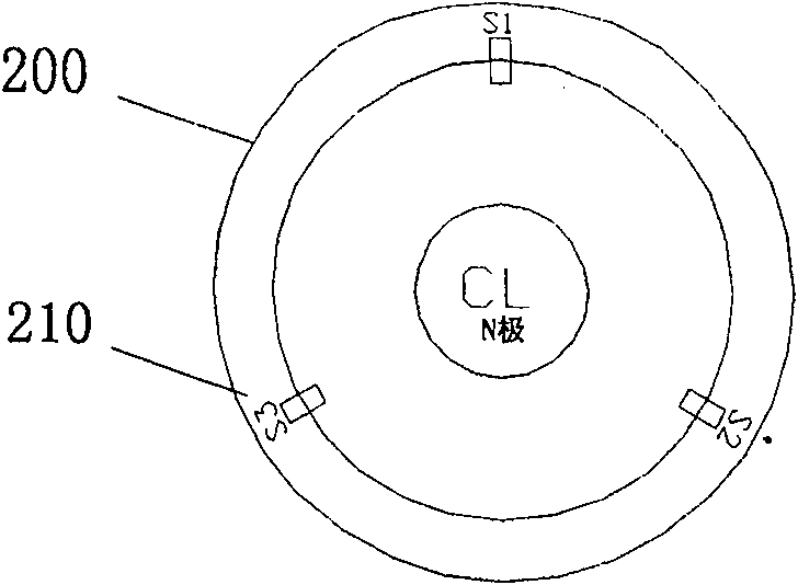
[0019] Such as figure 2 As shown, an inductive coding switch includes an inductive switch board 200 and an inductive knob 202, the inductive switch board 200 and the inductive knob 202 are placed on both sides of an operation panel 204 (the operation panel here is a glass panel), and passed through the The first permanent magnet CL in the center of the inductive switch plate 200 and the second permanent magnet CH in the center of the inductive knob 202 are attracted to each other, and the inductive switch plate 200 includes n (n>= 3) Hall switch 210, the induction knob 202 includes a base 208 for fixing the second permanent magnet, a knob 206 mounted on the base 208 and m (m) evenly distributed on the same circumference of the knob inner shell is an even number of permanent magnets, by rotating the knob 206 a magnetic field that changes relative to the inductive switch plate 200 is generated.

[0020] In order to ensure that two or more Hall switches 210 will not be turned o...


PUM


Abstract

The inductive addressable switch includes inductive switchboard and inductive knob. Being positioned on two side of the operation panel, the switchboard and knob are located by attractive interactionbetween first permanent magnet at center of the inductive switchboard and second permanent magnet at center of the inductive knob. The inductive switchboard includes n (larger than or equal to 3) pieces Hall switches distributed on same circumference evenly. The inductive knob includes base in use for fixing up second permanent magnet, knob instilled in the base, and m (even number) pieces of permanent magnet distributed on same circumference of inner casing of knob evenly. Rotating the knob generates magnetic field variational to the inductive switchboard. The invention does not need to makehole on body case of electrical installation so as to keep integrality of installation, and reach purpose of moistureproof and anticreep.

Description

technical field [0001] The present invention relates to a switch, and more particularly, to an inductively coded switch. Background technique [0002] Existing mechanical coding switches (such as figure 1 shown), including the encoding switch shaft 102, the knob 104, the fixing nut 106, the electrical equipment casing (or operation panel) 108, the through hole 110 on the casing, the mechanical encoding switch body 100 and the internal mechanical switch lead-out pin 112. During use, it is necessary to open a hole on the casing of the electrical equipment so that the encoding switch shaft 102 protrudes out of the operation panel 108 of the electrical equipment through the through hole 110 on the casing 108 , and the knob 104 is installed on the shaft 102 . [0003] Disadvantages of using mechanical coding switches: due to the need to open holes in the electrical equipment, the integrity of the electrical equipment shell will be destroyed, and the strength of the shell will al...

Claims


Application Information

Patent Timeline
Patent Type & Authority Patents(China)
IPC IPC(8): H03K17/95G01B7/30
Inventor 马伟黎志
Owner SHENZHEN TOPBAND CO LTD
Why Eureka
Try Eureka