System for controlled operation of elevator in case of fire and method of controlled operation of elevator in case of fire

An elevator control and elevator technology, which is applied in the field of elevator fire control operation system, can solve the problems of transporting those who cannot be stranded to the evacuation floor, transporting those who cannot be stranded with fire alarms, etc.

Inactive Publication Date: 2007-07-25
MITSUBISHI ELECTRIC CORP
View PDF1 Cites 19 Cited by
  • Summary
  • Abstract
  • Description
  • Claims
  • Application Information

AI Technical Summary

Problems solved by technology

[0004] However, in the conventional elevator control operation system, it is not possible to transport the resident on floors other t

Method used


Image

  • System for controlled operation of elevator in case of fire and method of controlled operation of elevator in case of fire
  • System for controlled operation of elevator in case of fire and method of controlled operation of elevator in case of fire
  • System for controlled operation of elevator in case of fire and method of controlled operation of elevator in case of fire

Examples


Embodiment approach 1

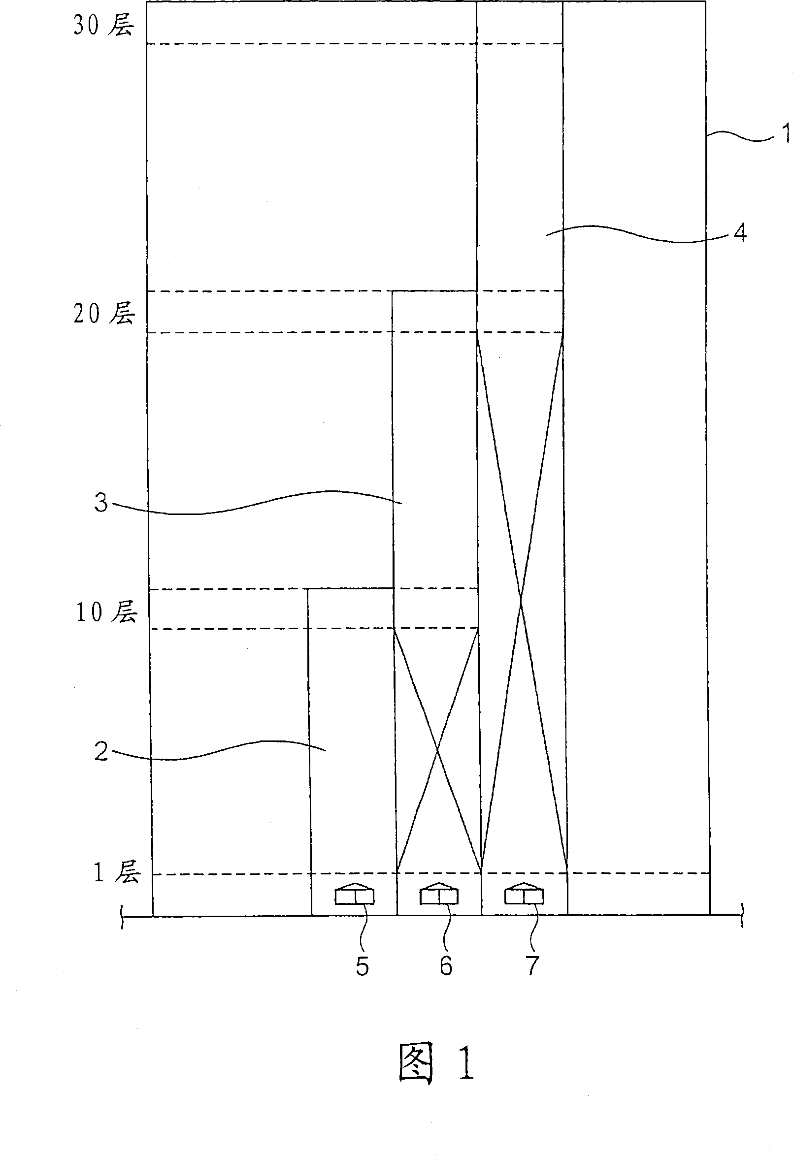
[0025] Fig. 1 is a schematic configuration diagram showing a building to which an elevator fire control operation system according to Embodiment 1 of the present invention is applied. In the drawing, a low-floor group elevator 2, a middle-floor group elevator 3, and a high-rise group elevator 4 are provided in a building 1 having multiple floors. The building 1 is a 30-story high-rise building having a basement (not shown). The lower-floor group elevator 2 has a car 5 capable of stopping on each of the first to tenth floors. The middle group elevator 3 has a car 6 that can stop at the first floor and each of the 10th to 20th floors. The high-rise group elevator 4 has a car 7 that can stop at each of the first floor and the 20th to 30th floors. In addition, the 10th and 20th floors are set as transfer floors.

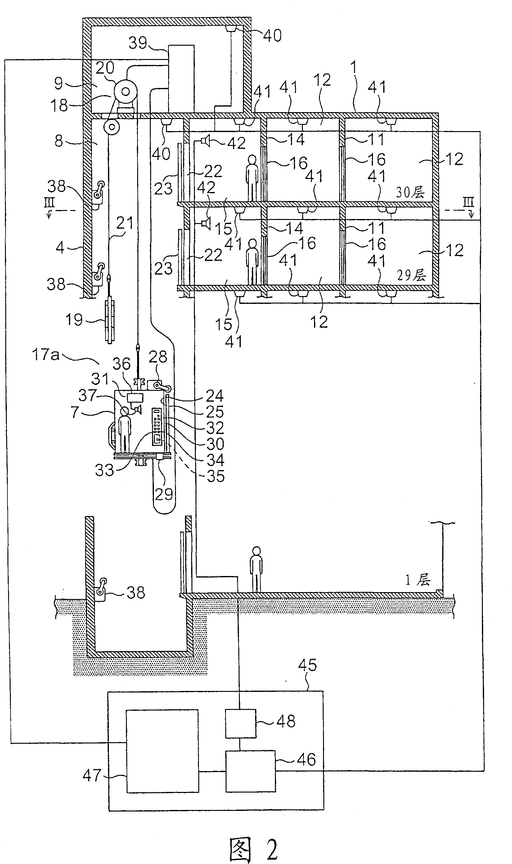
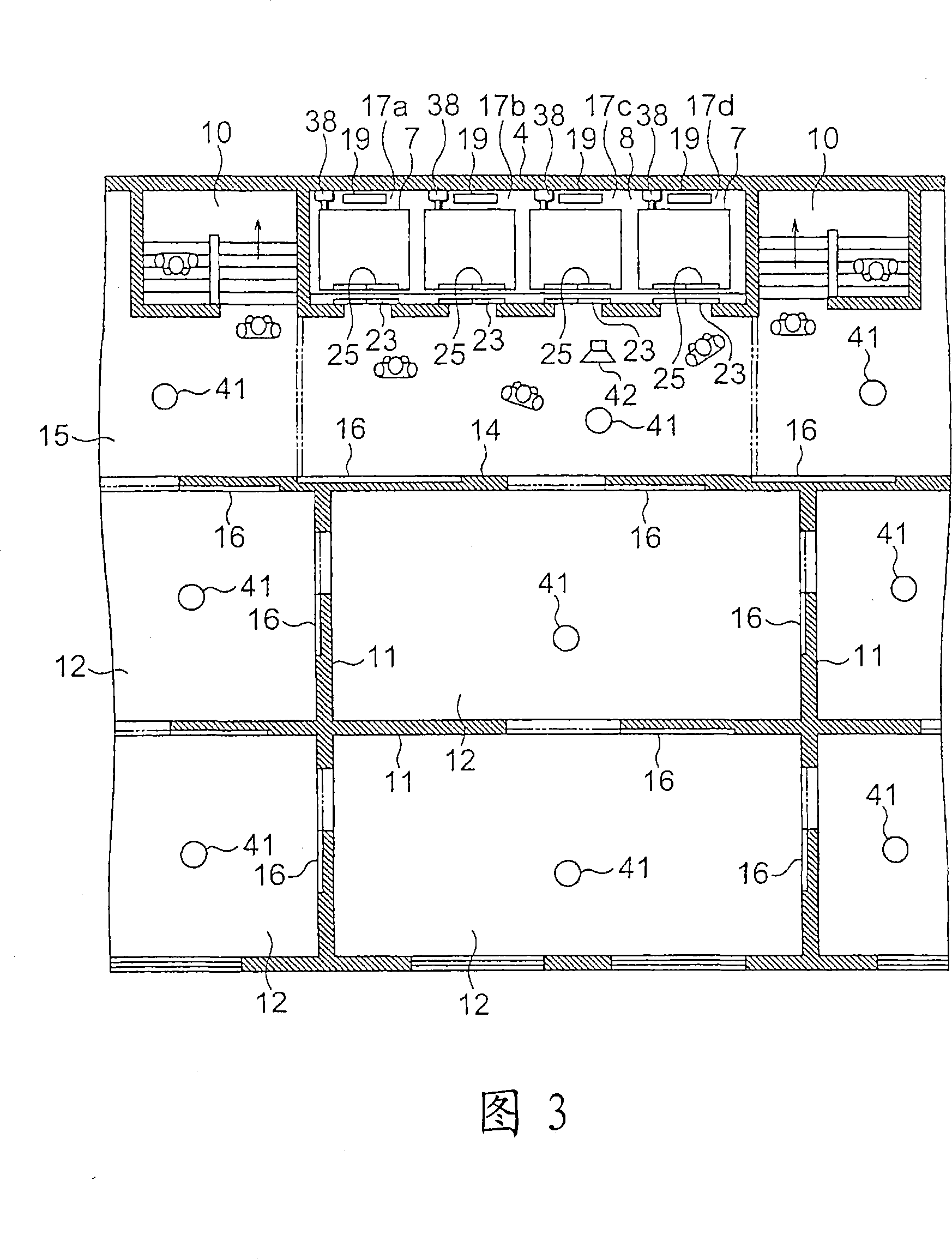
[0026] Fig. 2 is a longitudinal sectional view showing main parts of the building of Fig. 1 . In addition, FIG. 3 is a sectional view taken along line III-III in FIG...

Embodiment approach 2

[0150] Fig. 16 is a block diagram showing an elevator fire control operation system according to Embodiment 2 of the present invention. In the drawing, a building 1 is provided with an occupant management system 71 as a resident input means for measuring the number of resident people on each floor. The occupant management system 71 includes: personal authentication transmitting devices carried by occupants of the building 1; and a plurality of personal authentication receiving devices installed in halls 15 of each floor.

[0151] Personal authentication information such as the target floor of the occupant and the characteristic information of the occupant (healthy or disabled) are registered in advance in the personal authentication transmission device. As the personal authentication transmission device, for example, a key with a non-contact tag, a card with a non-contact tag, a mobile phone with a non-contact tag, etc. are used. In addition, in this example, the person regis...


PUM


Abstract

A system for controlled operation of an elevator in case of fire has an evacuation time calculation means for obtaining, based on information from a fire detector, a positional relationship between an elevator and the fire detector having performed fire detection operation and calculating an evacuation operation time based on the positional relationship; a fire floor specifying means for specifying, based on information from the fire detector, a floor where fire has occurred; a means for inputting the number of remaining persons so as to correspond to each floor; a schedule planning means for planning, based on information from the evacuation time calculation means, the fire floor specifying means, and the means for inputting the number of remaining persons, an evacuation operation schedule for each floor, the schedule being used when the remaining persons are transported to a floor for evacuation by evacuation operation in the evacuation operation time; a display means for displaying the contents of the evacuation operation schedule; and an elevator control means for controlling the operation of the elevator.

Description

technical field [0001] The present invention relates to an elevator fire control operation system and an elevator fire control operation method for evacuating occupants in a building when a fire occurs in a building. Background technique [0002] Conventionally, there has been proposed an elevator control operation system that controls the operation of the elevator so that the car can only stop when the fire alarm is activated during the period from when the fire alarm is detected to when a predetermined operation control condition is satisfied. floors and pre-specified refuge floors. In this conventional elevator control operation system, when a predetermined operation condition is satisfied, the car moves back and stops at the evacuation floor. (refer to patent document 1) [0003] Patent Document 1: Japanese Patent Application Laid-Open No. 58-52171 [0004] However, in the conventional elevator control operation system, the resident on floors other than the fire alarm...

Claims


Application Information

Patent Timeline
IPC IPC(8): B66B5/02
CPCB66B5/024B66B5/021
Inventor 河合清司
Owner MITSUBISHI ELECTRIC CORP
Why Eureka
Try Eureka