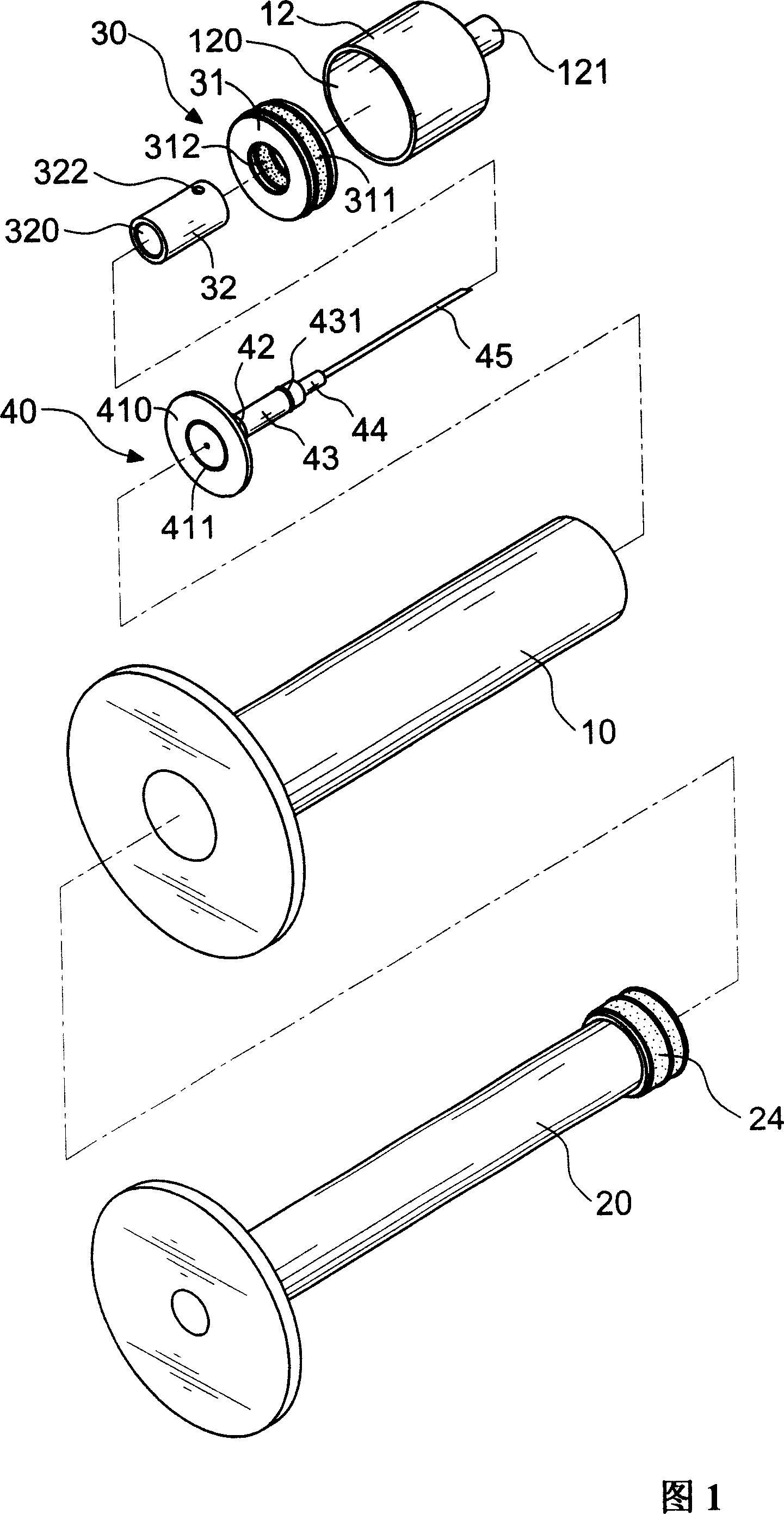
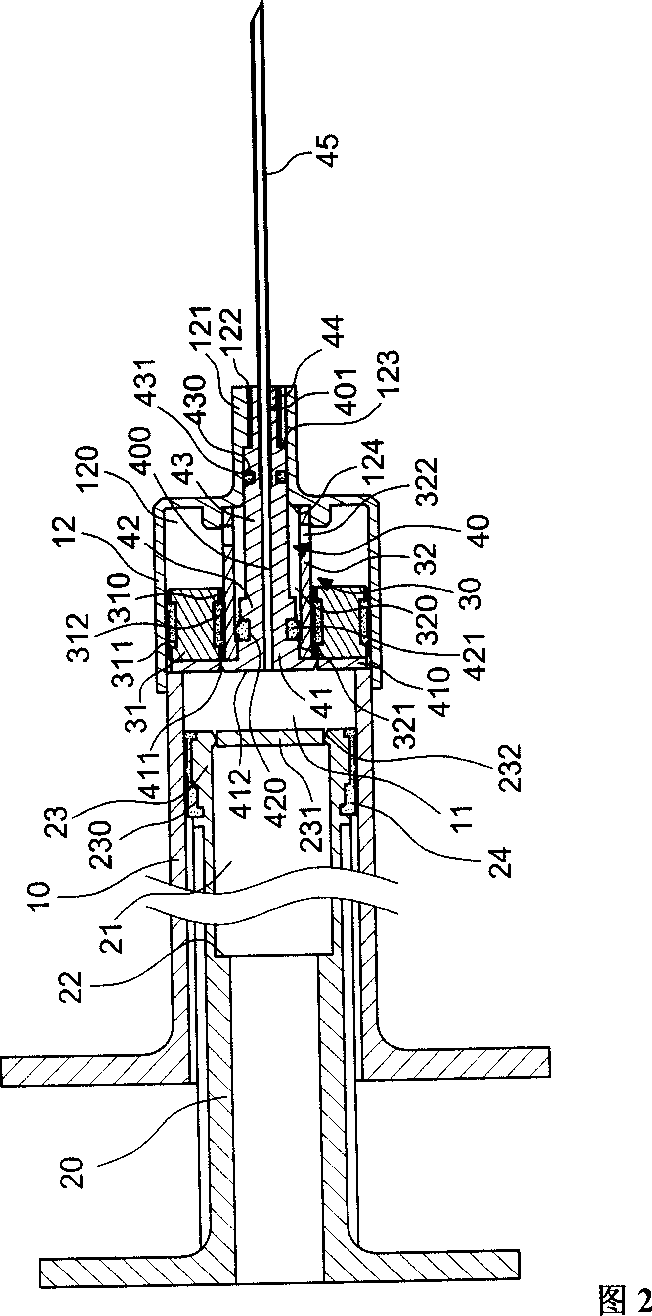
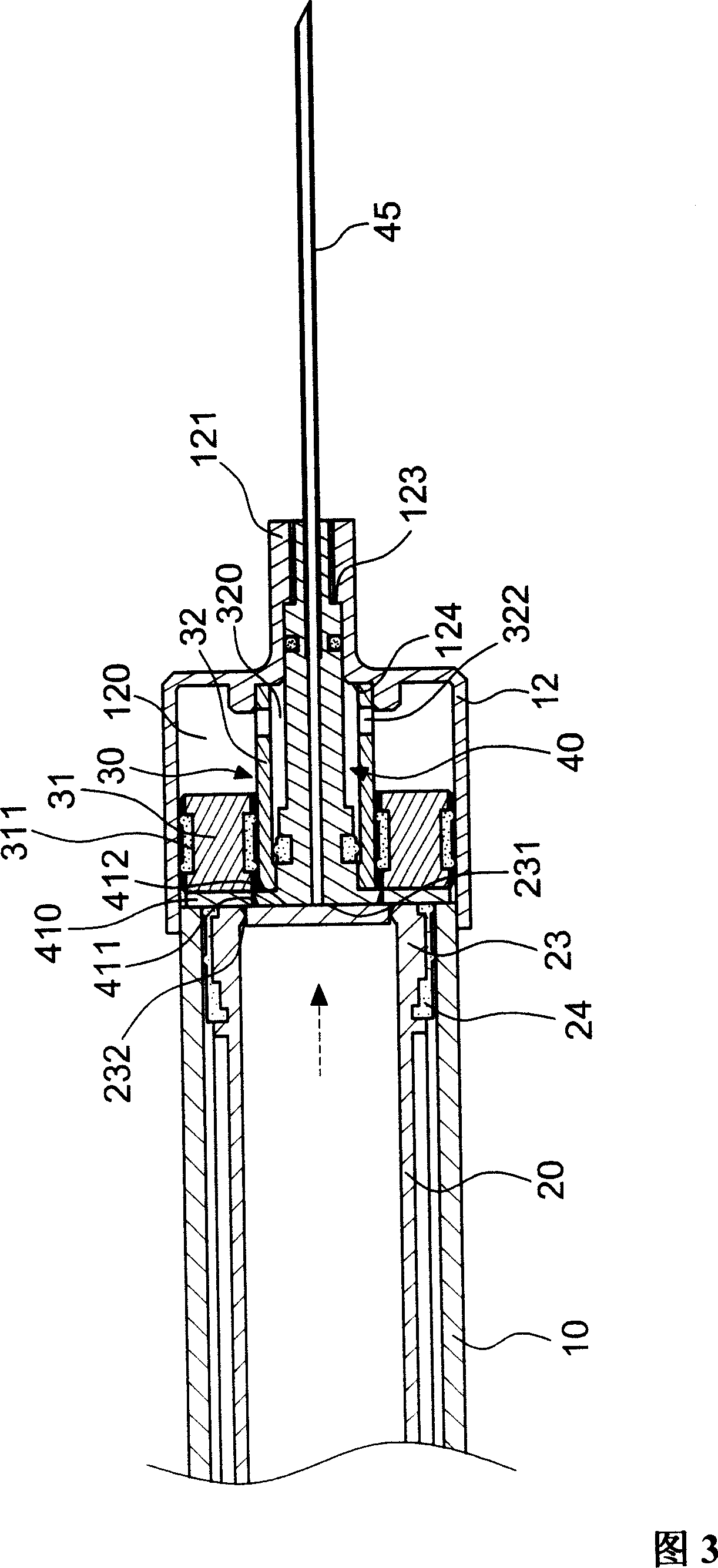
[0018] The present invention will be further described below in conjunction with the accompanying drawings
[0019] As shown in Figures 1 and 2, the safety syringe of the present invention mainly includes an outer tube 10, a push rod 20, a push assembly 30 and a needle seat 40, wherein:
[0020] The outer tube 10 is provided with a hollow channel 11 inside, and the outer tube sleeve 12 of the convex end 121 of the chamber 120 is provided at the end, and the convex end 121 is provided with a through hole 122 on the through hole 122. A first abutting surface 123 and A second abutting surface 124 having a diameter larger than that of the first abutting surface 123 is extended from one end.
[0021] The push rod 20 is disposed in the hollow channel 11 of the outer tube 10 and pushes in a tight fit. A accommodating cavity 21 is provided in the accommodating cavity 21 . The accommodating cavity 21 is provided with an abutting surface 22 , and an annular groove is provided on the periphery of the end portion 23 of the push rod 20 . 230 , so that the gasket 24 is sleeved, and the two ends of the end portion 23 are respectively provided with broken surfaces 231 of the concave edge 232 .
[0022] The push assembly 30 is sleeved in the outer sleeve 12 of the outer tube 10, and includes a piston 31 and a pump 32. The piston 31 is provided with a through hole 310, and the outer edge and the inner edge of the through hole 310 are provided with washers 311, 312. They are respectively connected with the outer sleeve 12 and the pump 32. The pump 32 is sleeved in the through hole 310 of the piston 31, with a hollow through hole 320 in it, a flange 321 at one end, and a peripheral edge at the other end of the pump 32. There are corresponding ventilation holes 322 .
[0023] The needle seat 40 is sleeved inside the pump 32 of the push assembly 30 , and one end extends with a first rod portion 41 , a second rod portion 42 , a third rod portion 43 and a fourth rod portion 44 . It has a small circular diameter, and is provided with a through hole 400 in the center and a receiving hole 401 at one end for the needle tube 45 to be placed in, wherein the outer edge of the first rod portion 41 forms a sleeve shape with the flange 321 of the pump 32, and one end extends with a seat The body 410, the side of the seat body 410 is provided with a broken surface 412 with a concave edge 411 to be sleeved on one side of the push assembly 30, and a ring groove 420 for the washer 421 to be accommodated is provided on the periphery of the second rod portion 42 to accommodate the washer 421. The third rod portion 43 is provided with a ring groove 430 on the periphery of the third rod portion 43, which can accommodate the gasket 431, so as to be pressed against the abutting surface 123 of the convex end 121 of the outer sleeve 12. The four-bar portion 44 is sleeved in the through hole 122 of the convex end 121 of the outer sleeve 12 .
[0024] As shown in Figures 3 and 4, when the safety syringe of the present invention is used for medical injection, the push rod 20 can push the end 23 of the push rod 20 from one end of the hollow channel 11 of the outer tube 10 to the other end by pushing force, Of course, when the end portion 23 of the push rod 20 is in contact with the seat body 410 of the needle seat 40 of the pusher assembly 30 sleeved on the outer edge, so that the end portion 23 of the push rod 20 abuts on the outer edge of the seat body 410, while the push rod 20 is pushed The broken surface 231 of the end portion 23 is pressed against the abutment surface 123 of the outer sleeve 12 by the third rod portion 43 of the needle hub 40 and pressed against each other, so that the broken surface 231 of the end portion 23 of the push rod 20 and the needle seat are pressed against each other. The folded surface 412 of 40 is provided with concave edges 232, 411, respectively, so that the thickness of the two folded surfaces 231, 412 is relatively thin, then the two folded surfaces 231, 412 are pressed against each other, respectively, and the end 23, the seat body respectively. 410 forms a disengaged state, at this time, the end 23 of the push rod 20 continues to advance, and the gas pressure (as shown by the arrow in FIG. 4 ) is pushed to the piston 31 of the push assembly 30 placed in the chamber 120 of the outer sleeve 12 advance, so that the gas pressure enters the hollow through hole 320 through the corresponding ventilation holes 322 at the other end of the pump 32, so that the gas pressure pushes the needle seat 40 back to the inside of the accommodating cavity 21 of the push rod 20 (as shown in FIG. 5 ). shown), so that the syringe 45 after injection can be safely stored.
[0025] In addition, the protruding end 121 of the outer sleeve 12 can be a structural design that can accommodate the needle tube 45 and can be placed in the accommodating cavity 21 of the push rod 20 without causing acupuncture hazards. In the embodiment shown in FIG. 6 , the outer sleeve 12 has an upper cover 125 arranged on the periphery of the convex end 121, so that the upper cover 125 can be sleeved on the convex end 121 of the outer tube sleeve 12, so that the upper cover 125 is used to close the hole 122 of the convex end 121, so as to prevent the needle tube 45 from being stored after being stored. It protrudes beyond the convex end 121, which greatly improves the safety effect without being stabbed in the process of recycling and handling.
[0026] To sum up, the safety syringe of the present invention can be directly injected into the body of the user, so that the user is not injured by the needle tube 45 of the needle seat 40, provides excellent safety, and allows the needle tube 45 to be used after injection When the end portion 23 of the push rod 20 pushes the piston 31 of the push assembly 30 forward, the broken surface 231 of the end portion 23 and the broken surface 412 of the needle seat 40 are pressed against each other by force, and are respectively connected with the end portion 23 and the seat body 410. The separation is formed, and the piston 31 continues to advance and the gas pressure in it is pushed back to push the needle seat 40 to retract into the accommodating cavity 21 of the push rod 20 , so as to achieve a better safe accommodating effect of the needle tube 45 .