
Enclosed air passage system for grinding roll

An air duct and grinding roller technology, applied in the field of the air duct system of the grinding roller, can solve the problems of the pressure loss of the air duct system, the failure of the seal of the grinding roller, and the rupture.

Active Publication Date: 2007-08-01
沈阳吉大重型机械有限公司
View PDF0 Cites 7 Cited by
  • Summary
  • Abstract
  • Description
  • Claims
  • Application Information

AI Technical Summary

Problems solved by technology

The common grinding roller sealing air duct system uses an external fan to generate positive pressure air, which is sent to the mill from the external pipeline, and the circular pipeline installed inside the mill is connected with a joint bearing, and the circular pipeline is connected and set by the joint bearing. In the air inlet pipeline on the grinding roller bracket, the positive pressure air of the air inlet pipeline directly enters the grinding roller bracket, and the gap formed between the grinding roller bracket, the grinding roller and the rotating parts driven by the grinding roller is the outlet of the air duct system. Due to the vibration of the mill during work, the wear of the joint bearing during use will cause air leakage, resulting in pressure loss in the air duct system, which will cause the seal of the grinding roller to fail. Vibration and the scouring of the internal dust-containing wind, the pipe wall is ground and leaked, and even in the case of severe vibration of the mill, it will cause rigid damage and rupture, resulting in failure of the grinding roller seal
The current methods to solve this problem are all focused on improving the precision and material of the joint bearing, and using the protection pipeline, etc. Although these methods can improve the reliability of the grinding roller seal to a certain extent, they add a great deal of trouble to the installation. Difficulty, but also greatly increased the investment in equipment

Method used


Image

  • Enclosed air passage system for grinding roll
  • Enclosed air passage system for grinding roll

Examples


Embodiment Construction

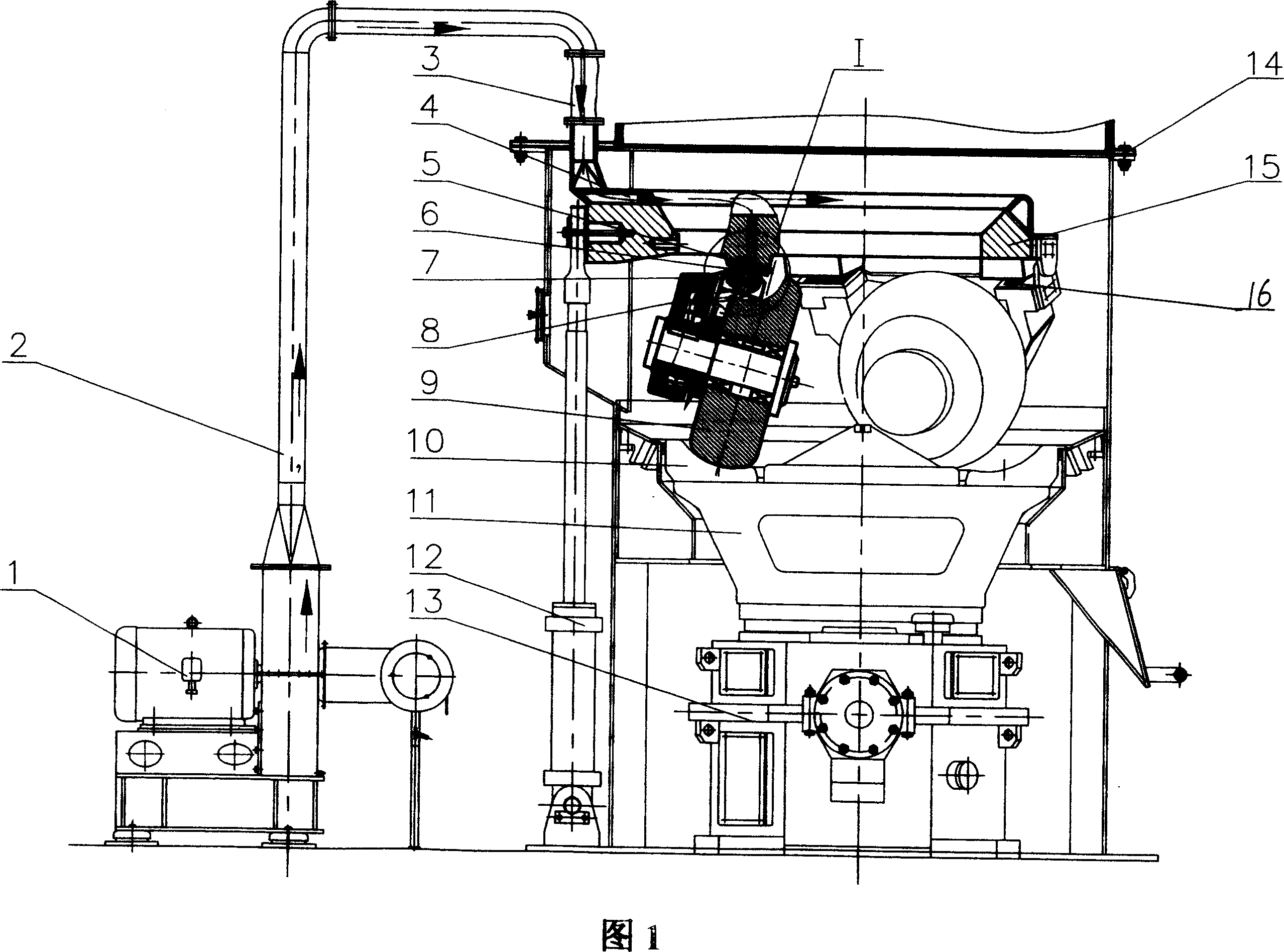
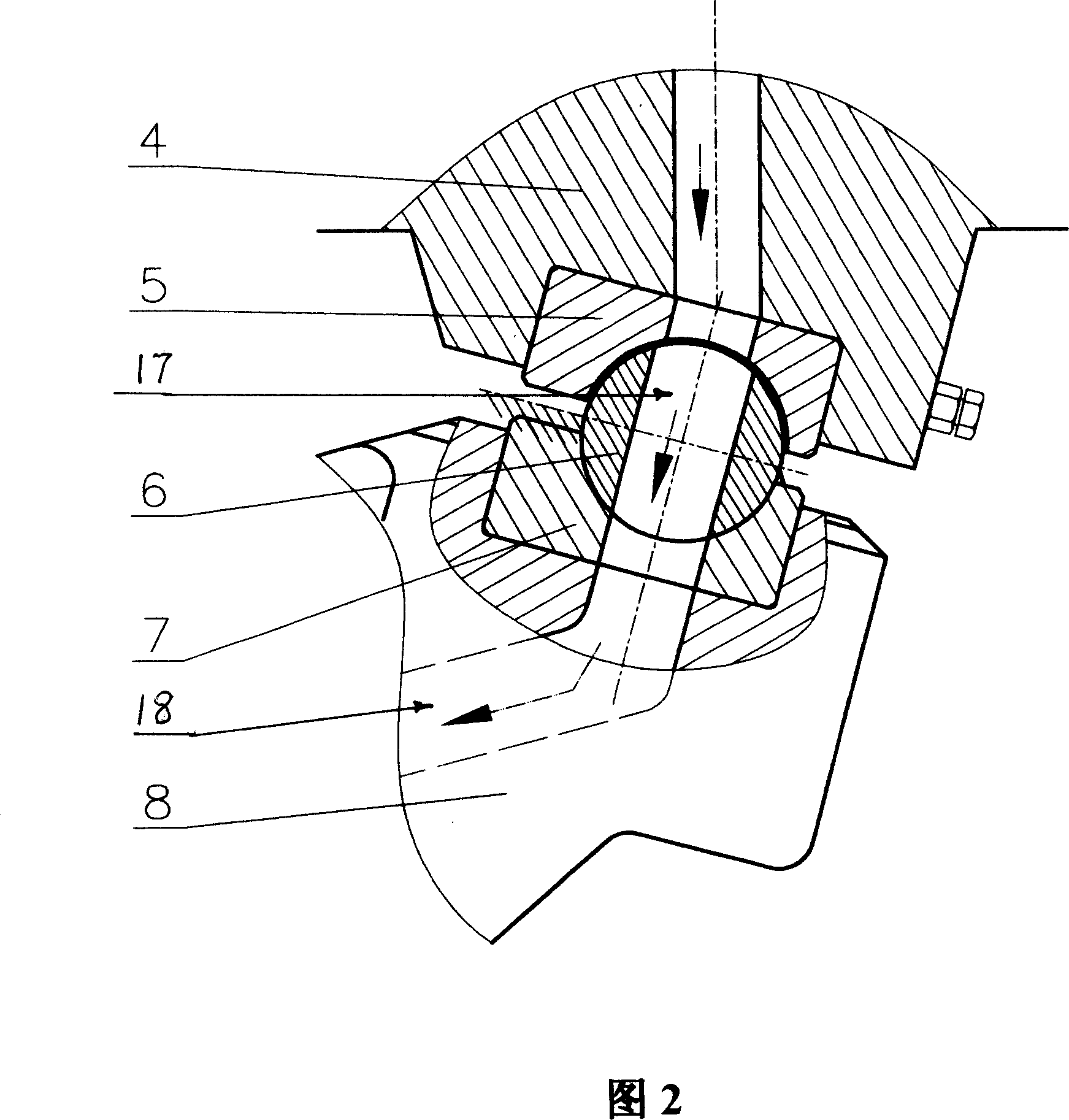
[0012] Please refer to Figure 1 or Figure 2, the grinding roller sealing air duct system of the present invention includes a fan 1, an external pipeline 2, a soft connection 3, a fixed pipeline 4 on the pressure frame, an upper roller seat 5, a sealing roller 6, The lower roller seat 7, the grinding roller bracket 8, the grinding roller 9, the fan 1 is arranged outside the mill, the external pipeline 2 is connected with the fan 1, and the pipeline 4 fixed on the pressure frame inside the mill is connected through a soft connection 3 , the fixed pipeline 4 on the pressure frame is fixed on the upper end of the pressure frame 15 of the internal parts of the mill, the pressure frame 15 is a triangular structure, the fixed pipeline 4 on the pressure frame is fixed on its upper end, and the lower end is processed into the upper roller seat 5 (also can be Separately process the upper roller seat 5 and put it into the pressure frame 15), and on each corner of the pressure frame 15 tri...


PUM


Abstract

Grinding roller sealed air duct system includes fan, external pipe lines, soft connectivity, pipe lines fixed on pressure framework, upper roller seat, sealing roller, lower roller seat, grinding roller frame and grinding roller; its characteristics is said upper roller seat, sealing roller and lower roller seat combine sealed air duct, the sealed air duct is connected with air holes of grinding roller frame. The fan transmits positive pressure wind into the sealed air duct combine by upper roller seat, sealing roller and lower roller seat through external pipe lines and pipe lines fixed on pressure framework, and blowout wind through the air holes of grinding roller frame and the chine between grinding roller frame, grinding roller and grinding roller frame driving rotating components.The invention solves the problem of grinding roller seal failure because of vibration joint wear, while solves the problems of the grinding leakage of loop pipe line and grinding roller frame air-supply line because of long-time mill vibration and dust wind erosion, or rigidity injury even breach lead by mill shape vibration. The invention not only saves a lot of investment, reduces costs, and is a highly reliable grinding roller sealed air duct system.

Description

(1) Technical field [0001] The invention relates to a mill, in particular to an air duct system for grinding rollers in the mill. (2) Background technology [0002] The grinding roller sealing air duct system is to use the external pipeline to guide the positive pressure air into the grinding roller bracket, and it is sprayed out from the gap between the grinding roller bracket and the grinding roller and the rotating parts driven by the grinding roller, and the pressure of the ejected gas is Prevent external dust gas from entering the grinding roller to achieve a sealing effect. The common grinding roller sealing air duct system uses an external fan to generate positive pressure air, which is sent to the mill from the external pipeline, and the circular pipeline installed inside the mill is connected with a joint bearing, and the circular pipeline is connected and set by the joint bearing. In the air inlet pipeline on the grinding roller bracket, the positive pressure air ...

Claims


Application Information

Patent Timeline
IPC IPC(8): B02C23/28B02C15/00
Inventor 杨建勋
Owner 沈阳吉大重型机械有限公司
Learn More