Hydraulic car leg oil cylinder

A technology of oil cylinders and legs, which is applied in the field of hydraulic control systems, can solve problems such as hydraulic leg oil cylinder seal failure and piston rod damage, and achieve the effects of improving work reliability, reducing wear, and solving mechanical damage

Active Publication Date: 2017-11-17
BEIJING MECHANICAL EQUIP INST
View PDF5 Cites 0 Cited by
  • Summary
  • Abstract
  • Description
  • Claims
  • Application Information

AI Technical Summary

Problems solved by technology

[0005] In view of the above analysis, the present invention aims to provide a hydraulic leg cylinder, which solves the problems of mechanical damage on the surface of the piston rod and failure of the seal of the hydraulic leg cylinder in the prior art due to lateral force

Method used


Image

  • Hydraulic car leg oil cylinder
  • Hydraulic car leg oil cylinder

Examples


Embodiment 1

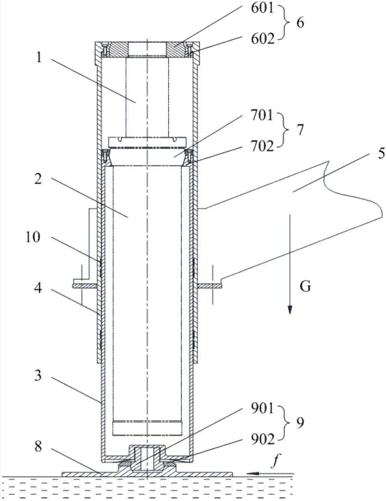
[0029] This embodiment provides a hydraulic leg cylinder, see figure 2 , which includes a piston rod 1, an oil cylinder 2 sleeved on the outside of the piston rod 1, an inner sleeve 3, and an outer sleeve 4 sleeved on the outside of the inner sleeve 3; the oil cylinder 2 is slidingly connected to the piston rod 1, and the inner sleeve The sleeve 3 is slidingly connected with the outer sleeve 4, and the oil cylinder 2 is located in the inner sleeve 3; the top of the outer sleeve 4 is connected with the top of the piston rod 1, and the top of the inner sleeve 3 is connected with the top of the oil cylinder 2; when in use, the outer The sleeve 4 is fixedly connected to the connecting beam 5 of the vehicle leg, and the bottom end of the inner sleeve 3 is in contact with the ground.

[0030] It should be noted, figure 2 Among them, G represents the direction of gravity, and f represents the direction of friction.

[0031] During implementation, the piston rod 1 is gradually str...


PUM


Abstract

The invention relates to a hydraulic car leg oil cylinder, and belongs to the technical field of hydraulic control systems. The problems that in the prior art, due to side force, the surface of a piston rod is mechanically damaged, and seal of a hydraulic car leg oil cylinder fails are solved. The hydraulic car leg oil cylinder comprises a piston rod, an oil cylinder arranged on the outer side of the piston rod in a sleeving manner, an inner sleeve and an outer sleeve arranged on the outer side of the inner sleeve in a sleeving manner; the oil cylinder is in sliding connection with the piston rod, the inner sleeve is in sliding connection with the outer sleeve, the oil cylinder is located in the inner sleeve, the top end of the outer sleeve is connected with the top end of the piston rod, the top end of the inner sleeve is connected with the top end of the oil cylinder, during use, the outer sleeve is fixedly connected with a car leg connecting beam, and the bottom end of the outer sleeve is in contact with the ground. The hydraulic car leg oil cylinder can be used for auxiliary supporting and leveling of a movable platform.

Description

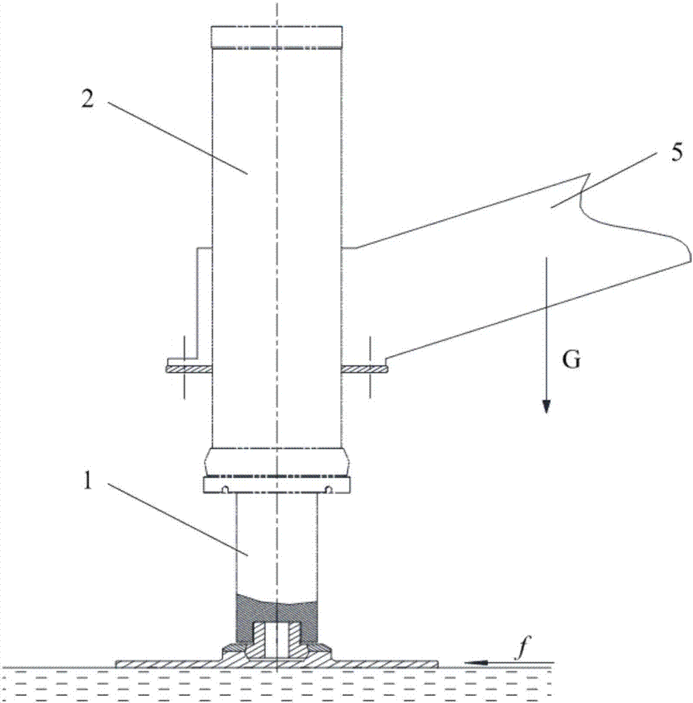
technical field [0001] The invention relates to a hydraulic control system, in particular to a hydraulic leg oil cylinder. Background technique [0002] A hydraulic leg cylinder is a type of hydraulic cylinder used for auxiliary support or leveling of a mobile platform, such as a construction vehicle. [0003] see figure 1 , the hydraulic leg oil cylinder of the prior art comprises piston rod 1 and oil cylinder 2, and oil cylinder 2 is sleeved on the outside of piston rod 1, and one end of piston rod 1 contacts with the ground, and oil cylinder 2 is fixedly connected with the mounting beam of car leg. During implementation, the piston rod 1 gradually extends out of the oil cylinder 2 under the action of hydraulic pressure, so that the oil cylinder 2 moves away from the ground, and further drives the mounting beam 5 of the vehicle leg to move away from the ground; or, the piston rod 1 moves in a direction away from the ground; Under the action, gradually insert the oil cyli...

Claims


Application Information

Patent Timeline
Patent Type & Authority Applications(China)
IPC IPC(8): F15B15/14F15B15/20B60S9/12
CPCB60S9/12F15B15/1423F15B15/1428F15B15/1457F15B15/1471F15B2215/30
Inventor 王鹏飞杨慧敏董凯高润鹏
Owner BEIJING MECHANICAL EQUIP INST
Why Eureka
Try Eureka