Integral engine multiple utility assembly for an automotive vehicle

A one-piece, engine technology, applied in the direction of the arrangement, application, and power unit of the cooling combination of the power unit, which can solve the problems of limiting the volume and weakening the utility of the assembly package, etc., and achieve the effect of good strength

Inactive Publication Date: 2011-03-16
FORD GLOBAL TECH LLC
View PDF2 Cites 0 Cited by
  • Summary
  • Abstract
  • Description
  • Claims
  • Application Information

AI Technical Summary

Problems solved by technology

This severely limits the volume of the vacuum chamber, presents problems of sealing the chamber itself due to the long length of the seal, and impairs the packaging utility of the assembly, as the stacked placement of the vacuum tanks increases the extent of the assembly to length in the engine compartment

Method used


Image

  • Integral engine multiple utility assembly for an automotive vehicle
  • Integral engine multiple utility assembly for an automotive vehicle
  • Integral engine multiple utility assembly for an automotive vehicle

Examples


Embodiment Construction

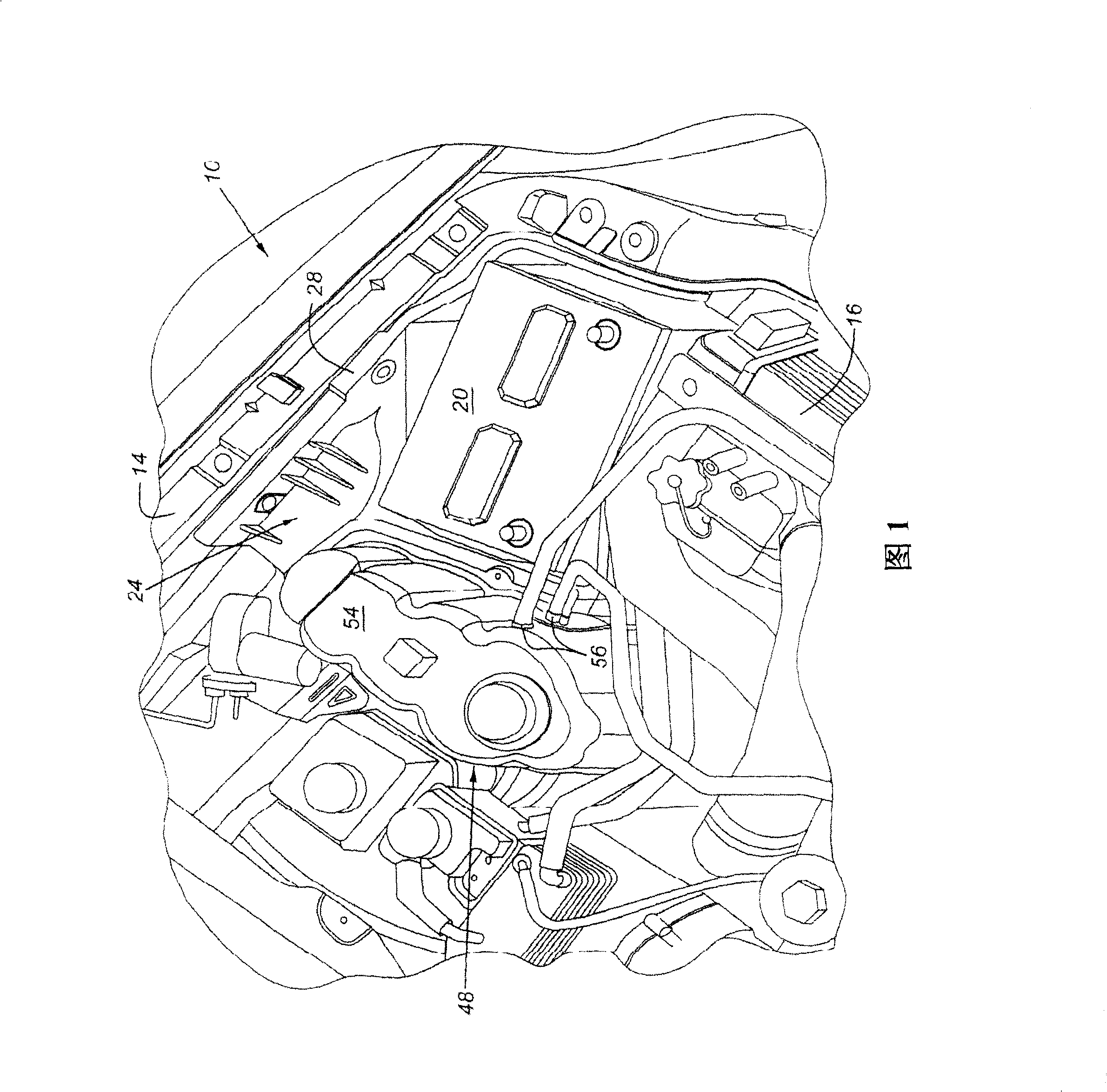
[0014] Such as figure 1 As shown, the vehicle engine compartment 10 includes a one-piece assembly 24 that is at least partially mounted to the fender 14 or another structure adjacent to the engine compartment 10 . The battery 20 is carried in the integrated assembly 24, and the integrated assembly also includes a coolant storage tank 48 and a vacuum storage tank 60 ( figure 1 not shown).

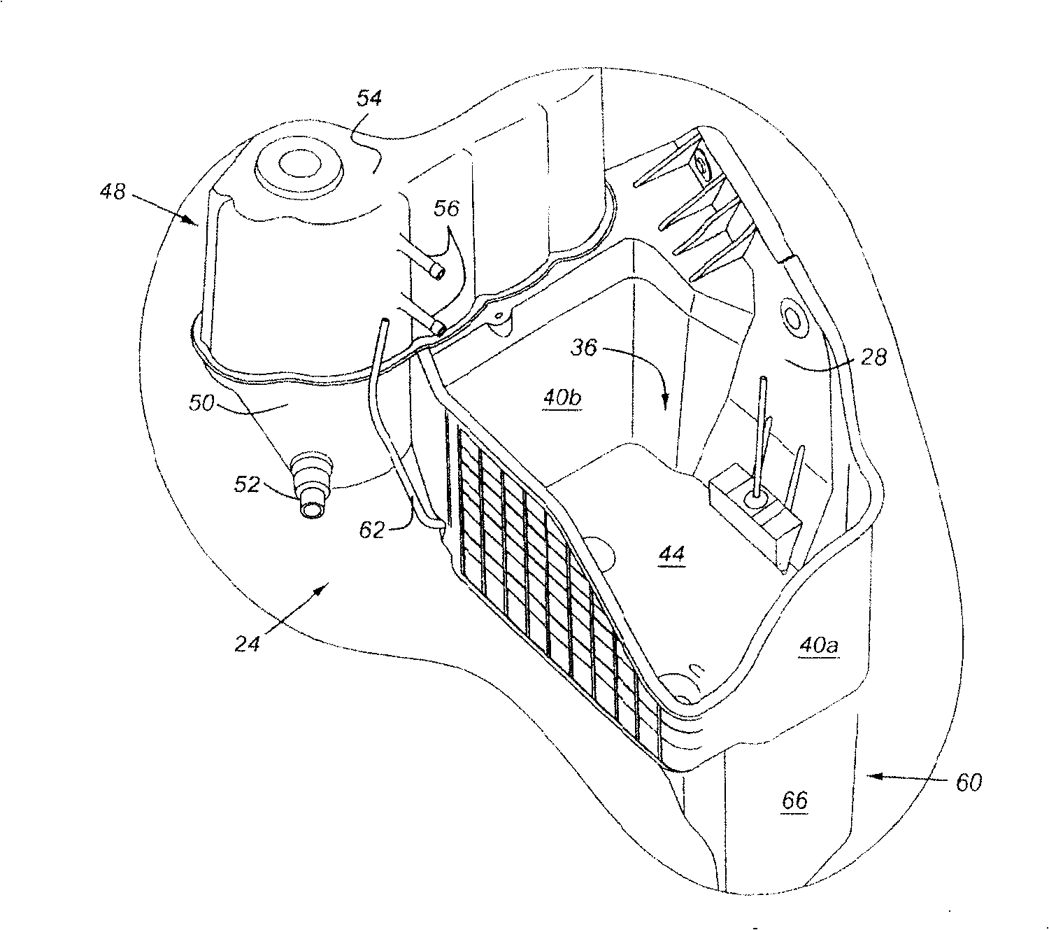
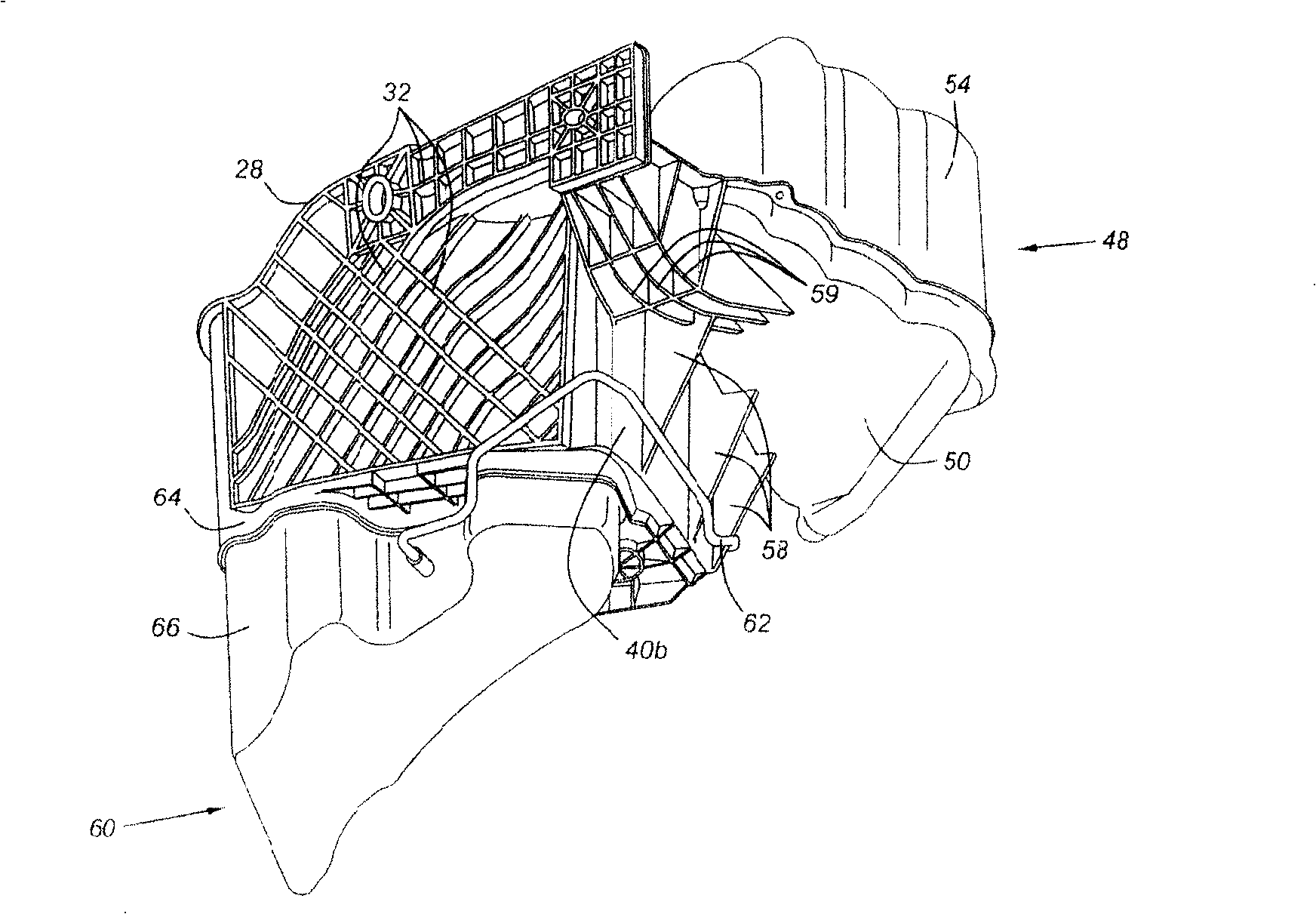
[0015] figure 2 One-piece assembly 24 is shown in which battery 20 is not secured. Mounting plate 28 mounts to fender 14 or to twin-tube tubing (not shown) of another structure, such as a frame, which may include a hydroformed tube assembly. The mounting plate 28 is reinforced by a series of integrated ribs 32 (such as image 3 shown). This gives the mounting plate 28 sufficient strength to function as a single fixture for the one-piece assembly 24 . This makes the task of securing the one-piece assembly a simpler task than would otherwise be the case requiring other securing points. ...


PUM


Abstract

An integral assembly for an automotive vehicle includes a battery tray, a coolant reservoir and a vacuum reservoir. The battery tray and portions of the coolant reservoir and vacuum reservoir are formed as a single molded part having shared partition walls, so as to provide superior strength, economy, and packaging efficiency.

Description

technical field [0001] The invention relates to a combined structure not only for housing a motor vehicle battery, but also for providing a tank for coolant and vacuum. Background technique [0002] Automotive component designers struggle to combine battery trays with other useful devices. US Patent No. 5,636,701 discloses an assembly of a battery tray and a vacuum tank. Unfortunately, the arrangement of the '701 patent does not represent an efficient use of space in the engine compartment because the vacuum reservoir is suspended by the battery mount pan and extends into the vehicle engine compartment. US Patent No. 6,439,329 discloses a battery tray and reservoir assembly, wherein the vacuum reservoir is located behind the rear wall of the battery tray. This severely limits the volume of the vacuum chamber, presents problems of sealing the chamber itself due to the long length of the seal, and impairs the packaging utility of the assembly, as the stacked placement of the...

Claims


Application Information

Patent Timeline
Patent Type & Authority Patents(China)
IPC IPC(8): B60R16/04B60R16/08B60K11/02
CPCB60R16/04Y10S224/902
Inventor 保罗·李·鲁斯金迈克尔·约翰·朗拉里·杜普伊斯
Owner FORD GLOBAL TECH LLC
Why Eureka
Try Eureka