
Ship capable of side-wise propelling and reducing wave-making resistance

A wave-making resistance and lateral propulsion technology, which is applied to ship propulsion, propulsion components, and steering with propeller slip flow instead of rudder. Eliminate turbulence and vortex resistance, enhance heading stability, and reduce the effect of wave-making resistance

Inactive Publication Date: 2007-08-01
黎观福
View PDF0 Cites 6 Cited by
  • Summary
  • Abstract
  • Description
  • Claims
  • Application Information

AI Technical Summary

Problems solved by technology

[0002] In the existing technology, the propeller of the ship is installed at the stern of the ship. Although the bow is made into a bulbous bow shape, the bow still causes relatively large wave-making during navigation, resulting in wave-making resistance, which seriously affects the sailing speed of the ship.
In order to enable the ship to have the function of lateral propulsion and to facilitate docking and leaving the pier, a propeller transverse device is currently used as side thrust, but this device only fixes the propeller in the tunnel and only produces a single side thrust function, which cannot be used as propulsion power for ship navigation. , and cannot be used as a steering device
When the ship is sailing, the existing side thruster cannot be used as propulsion power and steering, so it is always in an idle state, resulting in waste of equipment
At the same time, only one propeller can be installed to push a tunnel sideways at present, the force is limited, and it is extremely inconvenient to use
And if it is necessary to increase the force, it is necessary to increase the number of tunnels, but because the increase in the number of tunnels occupies the position of the cabin, there are still many defects in the existing lateral thrusters. In addition, the current full-turn propulsion devices are installed in Behind the stern, there is no retractable swing function. If it is installed in other parts, it will inevitably be damaged, so it is not suitable for use on the side of the bow and so on.

Method used


Image

  • Ship capable of side-wise propelling and reducing wave-making resistance
  • Ship capable of side-wise propelling and reducing wave-making resistance
  • Ship capable of side-wise propelling and reducing wave-making resistance

Examples


Embodiment Construction

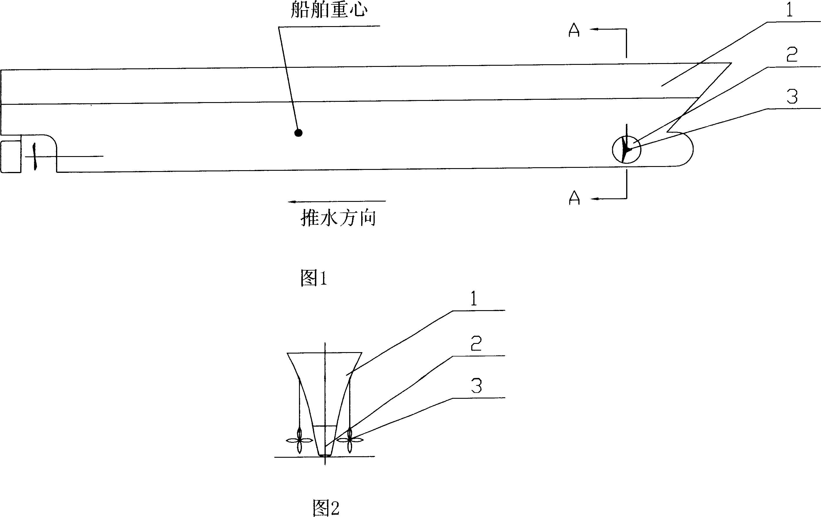
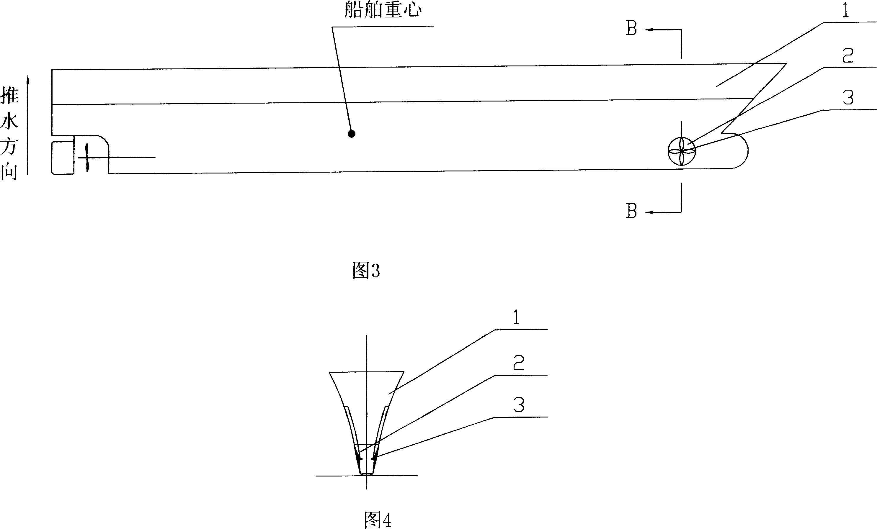
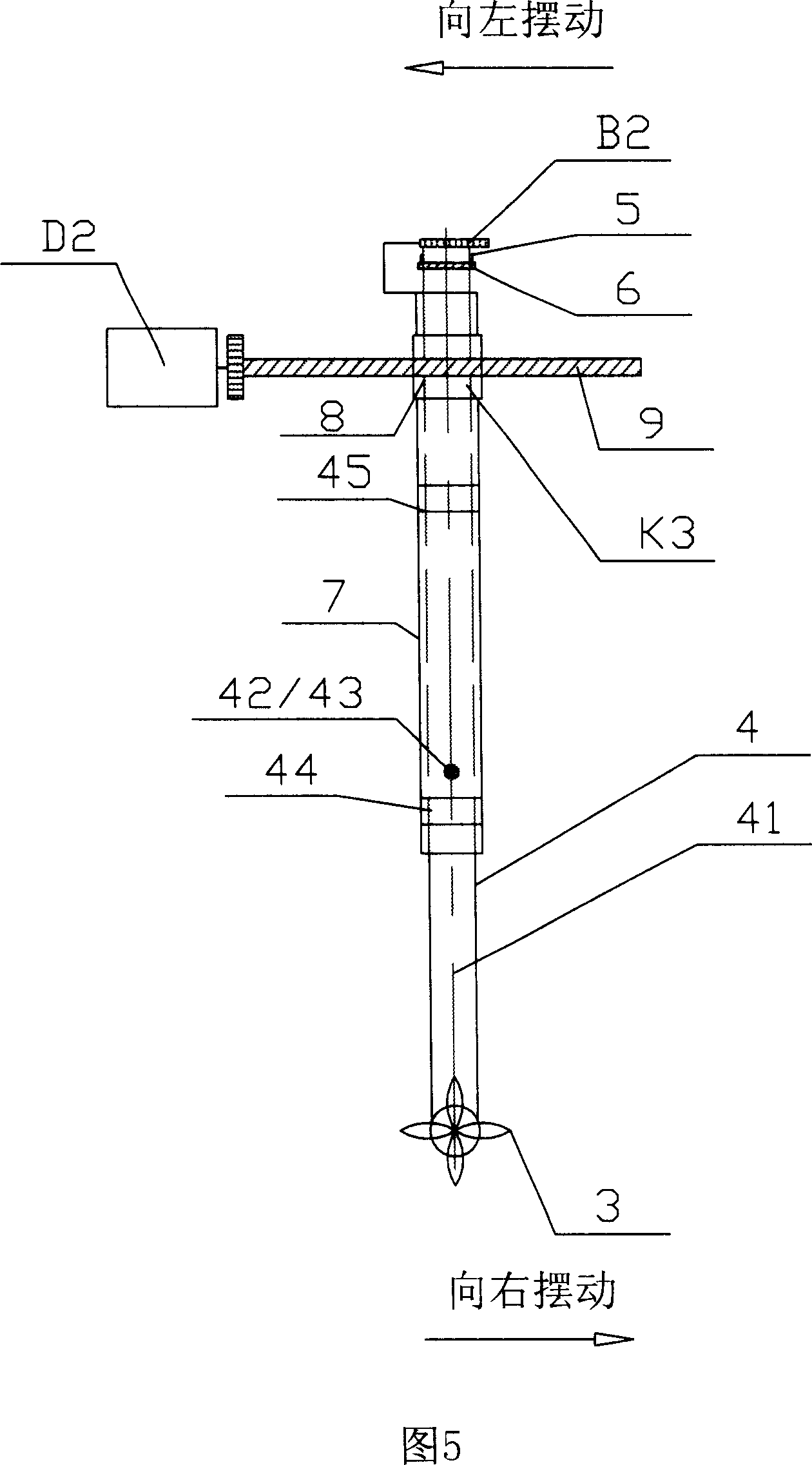
[0029] As shown in Figures 1 to 4, a ship that can be propelled laterally and can reduce wave-making resistance includes a hull 1, and several tunnels 2 that run through the hull 1 are set at the lateral position below the waterline of the hull 1, as shown in Figures 2 and 4. As shown in FIG. 4 , a propeller 3 is provided at both ends of each tunnel 2 , and a protective cover can be provided outside the propeller 3 , which can effectively prevent the propeller from being damaged by collisions with other objects. As shown in Fig. 5 and Fig. 6, the propeller 3 is connected with a driving device K1 for driving it to work and a full-turn device K2 for enabling the propeller 3 to generate thrust in any direction. The driving device K1 includes three pairs of gear transmission pairs A1, A2 / B1, B2 / C1, and C2, wherein the driving wheel A1 is coaxially installed with the power output shaft 10, the driven wheel A2 is coaxially installed with the driven shaft 11, and the driving wheel A1 ...


PUM


Abstract

The invention discloses a ship which can advance laterally and reduce the wave resistance. It includes ship body (1), the lateral position below the ship body (1) floating line is equipped with several tunnel (2) passing through the ship body (1), two ends of each tunnel (2) are equipped with propeller (3) respectively, the propeller (3) is connected with the drive device (K1) driving it work and the all-slewing equipment (K2) which can make the propeller (3) generate thrust towards any direction, it is also equipped with the lateral oscillating motion device(K3) which recalls and overhangs the propeller (3) into tunnel (2). The ship has simple structure, it can reduce the ship wave resistance effectively to pushing water navigation, as well as can make the propeller generate thrust towards any direction conveniently and recall or overhang the propeller into tunnel, it can effectively increase the cabin capacity of ship; it can realize turning conveniently and enhance the stability of ship course greatly.

Description

technical field [0001] The invention relates to a ship, in particular to a retractable ship that can be propelled laterally and can reduce wave-making resistance. Background technique [0002] In the existing technology, the propeller of the ship is installed at the stern of the ship. Although the bow is made into a bulbous bow shape, the bow still causes relatively large wave-making during navigation, resulting in wave-making resistance, which seriously affects the sailing speed of the ship. . In order to enable the ship to have the function of lateral propulsion and to facilitate docking and leaving the pier, a propeller transverse device is currently used as side thrust, but this device only fixes the propeller in the tunnel and only produces a single side thrust function, which cannot be used as propulsion power for ship navigation. , and cannot be used as a steering device. When the ship is sailing, the existing side thrusters are always in an idle state because they ...

Claims


Application Information

Patent Timeline
Patent Type & Authority Applications(China)
IPC IPC(8): B63H5/07B63H23/02B63H25/48
Inventor 黎观福
Owner 黎观福
Learn More