Supercharge Your Innovation With Domain-Expert AI Agents!

Illumination system and optical projection device

A lighting system and optical projection technology, applied in the direction of using projection device image reproducer, optics, projection device, etc., can solve the problems that the optical projection device cannot quickly display images, and the lighting system cannot quickly provide lighting beams, etc.

Inactive Publication Date: 2007-08-01
CORETRONIC
View PDF0 Cites 8 Cited by
  • Summary
  • Abstract
  • Description
  • Claims
  • Application Information

AI Technical Summary

Problems solved by technology

[0004] The purpose of the present invention is to provide a lighting system to solve the problem that the existing lighting system cannot quickly provide a certain brightness of the lighting beam when it is turned on
[0005] Another object of the present invention is to provide an optical projection device to solve the problem that the existing optical projection device cannot quickly display images after being turned on

Method used


Image

  • Illumination system and optical projection device
  • Illumination system and optical projection device
  • Illumination system and optical projection device

Examples


no. 1 example

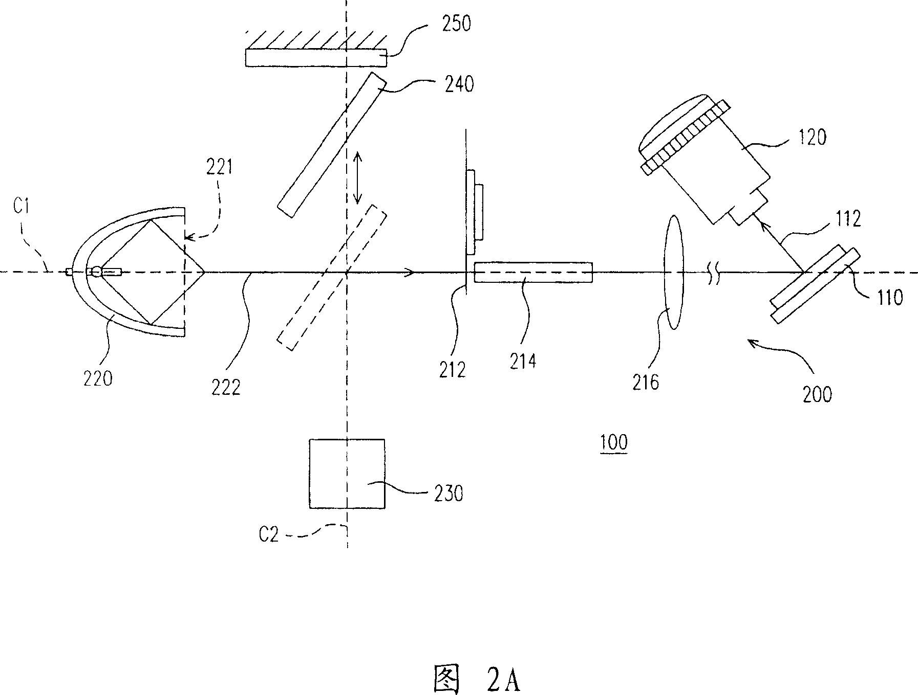
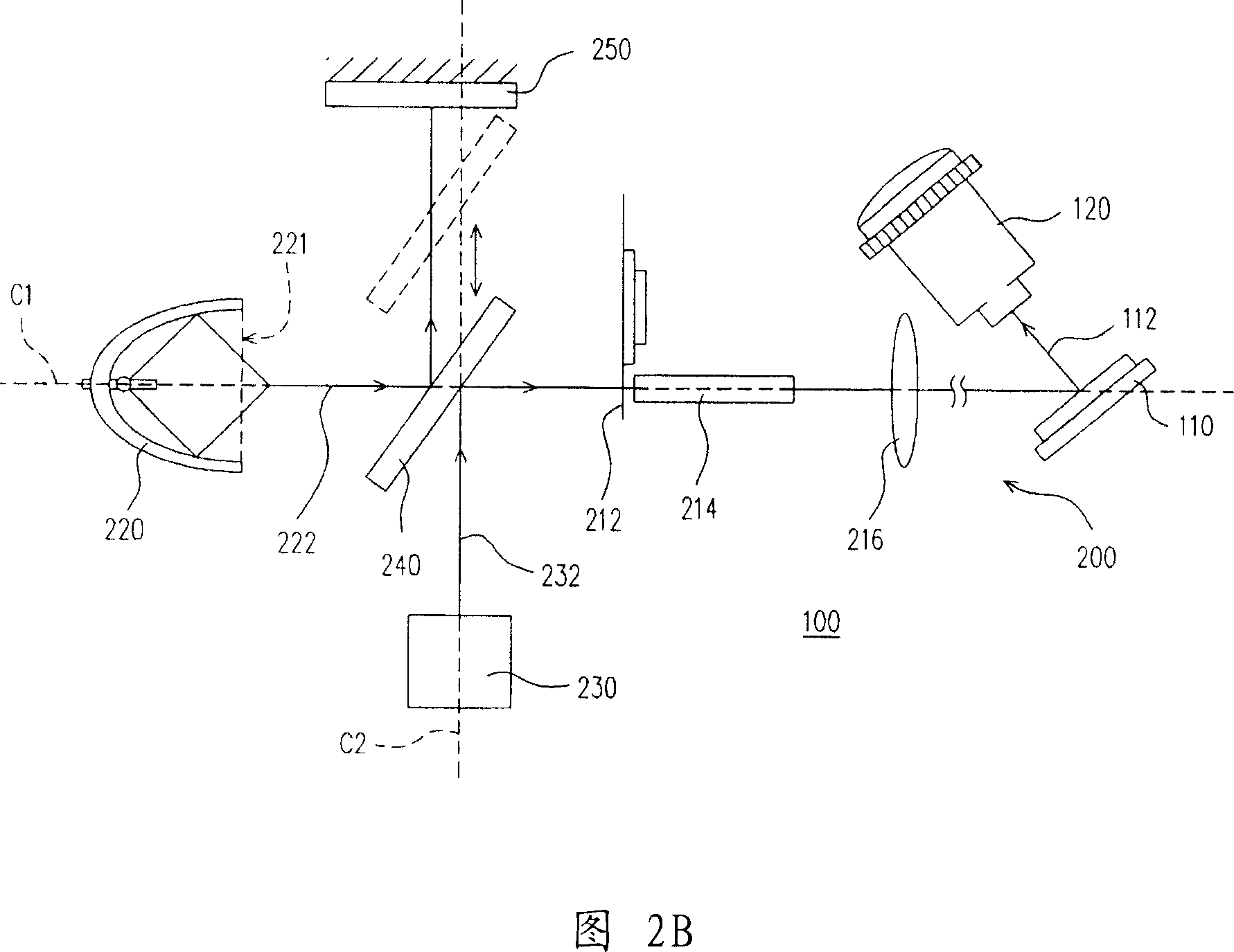
[0036] Please refer to FIG. 2A and FIG. 2B , which are schematic structural diagrams of the first embodiment of the optical projection device of the present invention. The optical projection device 100 of this embodiment includes a light valve 110 , an imaging system 120 and an illumination system 200 , wherein the light valve 110 is disposed between the imaging system 120 and the illumination system 200 . The lighting system 200 includes a main light source 220 , an auxiliary light source 230 , a light guide element 240 and at least one optical element (such as a color wheel 212 , a light integrating rod 214 , a lens 216 or a combination thereof). Wherein, each optical element has a light incident end respectively, and the main light source 220 and the auxiliary light source 230 are disposed beside the light incident end of the optical element closest to them, such as disposed beside the light incident end of the color wheel 212 . The main light source 220 has a light exit se...

no. 2 example

[0047] 5A and 5B are schematic structural views of an optical projection device according to a second embodiment of the present invention. Referring to FIG. 2A , FIG. 2B , FIG. 5A and FIG. 5B , the optical projection device 100 b of this embodiment is similar to the optical projection device 100 of the first embodiment, and only the differences will be described below. In the lighting system 200b of the optical projection device 100b of the present embodiment, the positions of the main light source 220 and the auxiliary light source 230 of the lighting system 200 of the first embodiment are exchanged. In other words, in the lighting system 200b of this embodiment, the main light source 220 is arranged on the second axis C2, and the auxiliary light source 230 is arranged on the first axis C1, and the auxiliary light source 230 has a light exit section 231, which is the same as The light incident ends of the color wheel 212 are opposite to each other. In addition, the light gui...


PUM


Abstract

This invention discloses one light system, which comprises optical parts, one main light source, one aid light source and one light conductive part, wherein, the optical element has one incidence end and the main source and aid source are set by side of optical element; main light source is to provide one main beam and the aid one to provide aid beam to achieve maximum brightness time; light conductive part is to cut off main beam and aid beam path to transfer to optical element to provide one brightness light beam.

Description

technical field [0001] The invention relates to an illumination system and an optical projection device, in particular to an illumination system with an auxiliary light source and an optical projection device with the illumination system. Background technique [0002] Since the ultrahigh pressure mercury lamp (UHP) has the advantages of high luminous efficiency, high light collection efficiency and long service life, the common projectors and rear projection television (RPTV) lighting systems currently on the market , mainly using ultra-high pressure mercury lamps as the lighting source. [0003] Please refer to Figure 1, which shows the relationship between the luminescence level and time after the ultra-high pressure mercury lamp is turned on. Generally speaking, ultra-high pressure mercury lamps require a long warm-up time (idling time). It can be seen from Figure 1 that it takes at least five minutes for the ultra-high pressure mercury lamp to reach 100% luminescence (i...

Claims


Application Information

Patent Timeline
Patent Type & Authority Applications(China)
IPC IPC(8): G02B27/18G03B21/00H04N5/74H04N9/31
Inventor 王思克
Owner CORETRONIC
Features
  • R&D
  • Intellectual Property
  • Life Sciences
  • Materials
  • Tech Scout
  • Unparalleled Data Quality
  • Higher Quality Content
  • 60% Fewer Hallucinations
Learn More