Terminal fixing structure

A terminal fixing and fixing column technology, which is applied in the direction of fixing/insulating contact components, electrical components, coupling devices, etc., can solve the problems of the contact end of the terminal 12 sinking, the bonding force of the fixing patch 17 being weakened by heat, and affecting the fixing of the terminal 12, etc.

Inactive Publication Date: 2007-08-01
QUANTA STORAGE INC
View PDF0 Cites 5 Cited by
  • Summary
  • Abstract
  • Description
  • Claims
  • Application Information

AI Technical Summary

Problems solved by technology

[0004] However, the aforementioned battery pack 10 needs to fix several conductive sheets 122 at intervals in the gel base 121 to form the terminals 12, and then insert the base 121 into the fixing hole 111, and indirectly use the base 121 to fix the terminals 12, which will not only increase the number of components and manufacturing cost, and it is necessary to set the positioning block 16 on one side, while the other side is supported by the fixed patch 17 pasted on the bottom case 11, which will also increase the complexity of assembly
In addition, when the battery core 14 is in use, the charge and discharge will generate heat, which will increase the temperature of the adjacent fixed patch 17, resulting in the weakening of the bonding force of the fixed patch 17 due to heat, which will affect the fixing of the terminal 12 and easily cause the terminal 12 The contact end sinks into the bottom shell 11 and fails
Therefore, there are still problems to be solved in the fixing of the terminals of the existing battery pack

Method used


Image

  • Terminal fixing structure
  • Terminal fixing structure
  • Terminal fixing structure

Examples


Embodiment Construction

[0016] In order to achieve the above object, the present invention adopts the technical means and its effects, and gives preferred embodiments, which are described as follows in conjunction with the drawings.

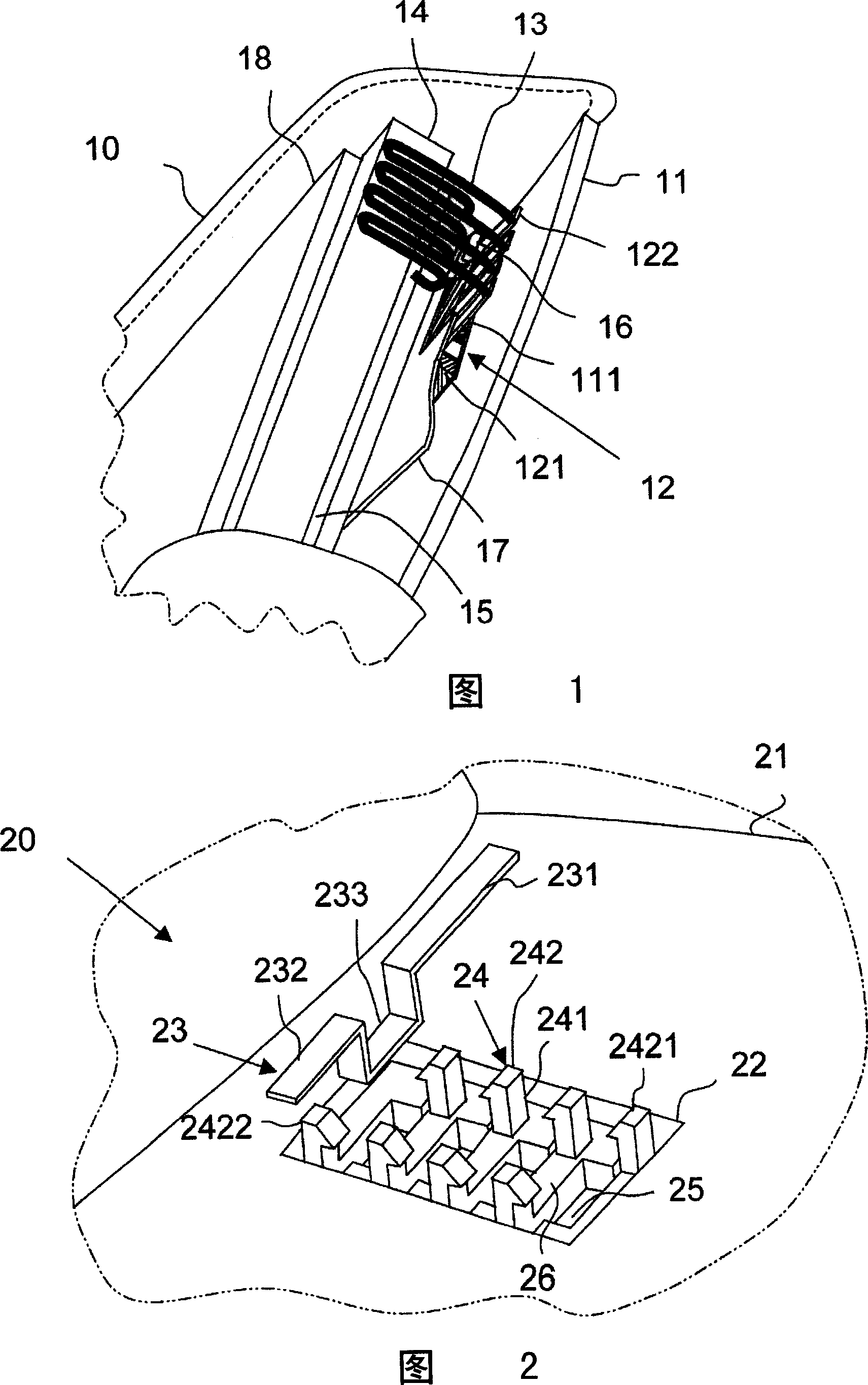
[0017] Please refer to FIG. 2 , which shows a terminal fixing structure 20 according to the first embodiment of the present invention, including a housing 21 , a positioning groove 22 , and a conductive sheet 23 . Mainly on the casing 21 of the electronic product, such as the bottom case of the battery, the positioning groove 22 is directly dug, and a plurality of conductive sheets 23 are directly embedded and fixed in the positioning groove 22 to form the terminal fixing structure 20 .

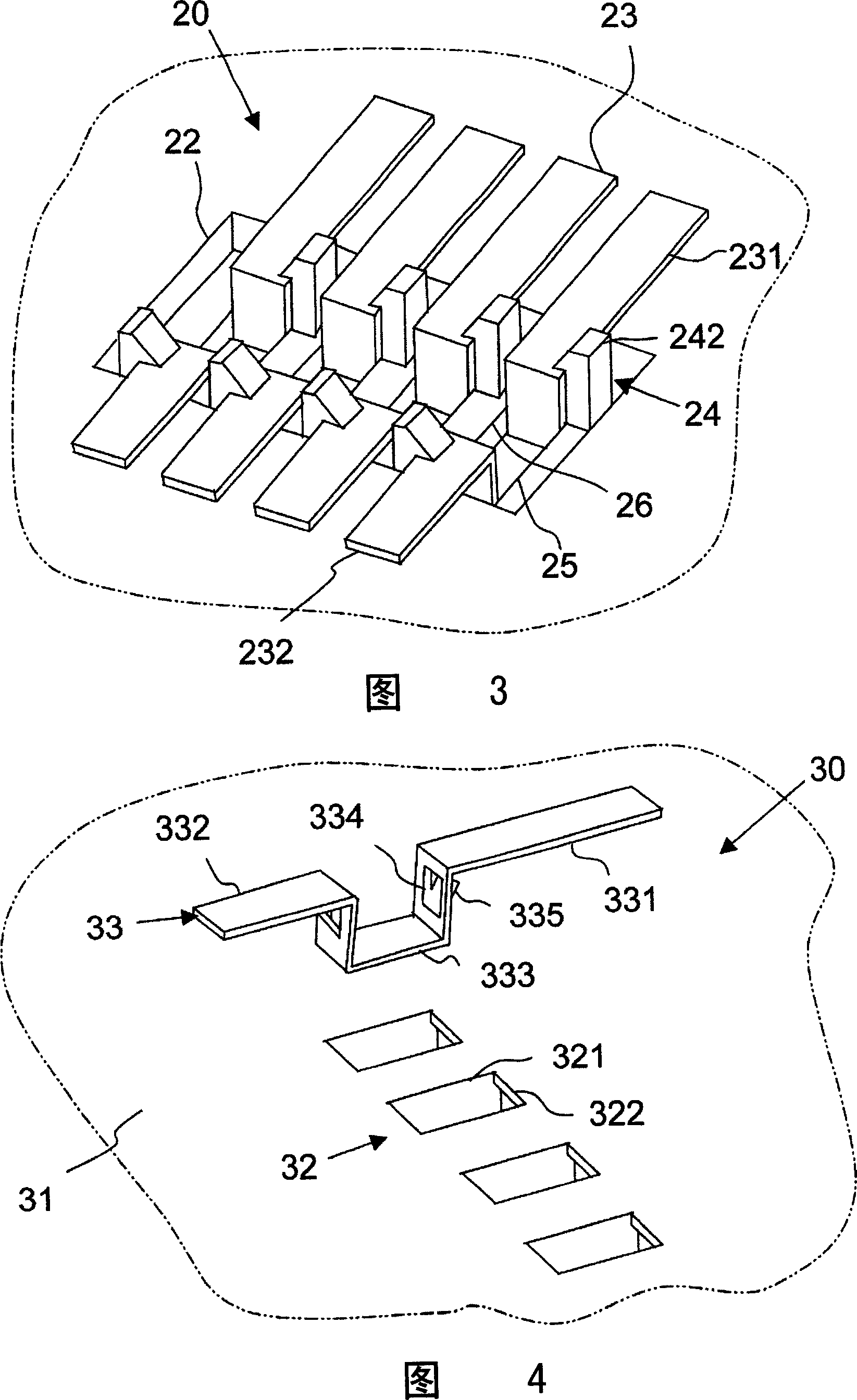
[0018] Wherein, the positioning groove 22 has a plurality of groups of conductive pieces 23 positioning units, the positioning unit is composed of snap buttons 24, through holes 25 and supporting ribs 26, etc., and the slightly N-shaped supporting ribs 26 are arranged in the positioning...


PUM


Abstract

A fixed structure for terminal is mounted in the shell of electronic product which includes positioning slot which is mounted on the shell, the positioning slot has several positioning elements, and the positioning elements have through holes, spring button and supporting rib, the side-wall of positioning slot protrudes several supporting ribs, the through holes are between the supporting ribs, and the spring buttons are mounted on the supporting ribs, and bulges upwards to expose the end of spring button. A spring button is mounted on each sides of supporting rib, and the ends of two spring buttons have different buckling directions. Several conductive plates is conductive long strip and has bending segment, which can embed in the through hole, and the end of spring button holds the edges of conductive sheet.

Description

technical field [0001] The invention relates to a terminal for electrical connection, in particular to a structure for fixing the terminal in a battery. Background technique [0002] Batteries are the most important source of power for electronic products, especially portable electronic products. To ensure that the terminals connected to the battery and electronic products produce a reliable electrical connection, the electronic products can maintain normal operation. As shown in FIG. 1 , the related battery pack 10 is formed by digging a fixing hole 111 in the bottom case 11 to embed and fix the terminal 12. The terminal 12 is formed by fixing several conductive sheets 122 at intervals on an insulating colloid base 121 After the terminal 12 is embedded in the fixing hole 111, part of the conductive sheet 122 will be exposed outside the bottom case 11 to form a contact end with the electronic product, and the conductive sheet 122 left inside the bottom case 11 will be conne...

Claims


Application Information

Patent Timeline
Patent Type & Authority Applications(China)
IPC IPC(8): H01R13/42H01R13/432
Inventor 张敬宏彭文宽
Owner QUANTA STORAGE INC
Why Eureka
Try Eureka