Eureka AIR delivers breakthrough ideas for toughest innovation challenges, trusted by R&D personnel around the world.

Fixing structure of voltage detection terminal

a technology of fixing structure and voltage detection terminal, which is applied in the direction of current conducting connection, cell components, electric devices, etc., can solve the problems of rattling and hindering the achievement of higher electrical connection, and achieve the effect of simple fixing structur

Active Publication Date: 2018-04-19
YAZAKI CORP
View PDF2 Cites 6 Cited by
  • Summary
  • Abstract
  • Description
  • Claims
  • Application Information

AI Technical Summary

Benefits of technology

The invention provides a way to keep a voltage detection terminal in place, preventing it from moving.

Problems solved by technology

The rattling hinders achievement of higher electrical connection therebetween.

Method used


Image

  • Fixing structure of voltage detection terminal
  • Fixing structure of voltage detection terminal
  • Fixing structure of voltage detection terminal

Examples


embodiment

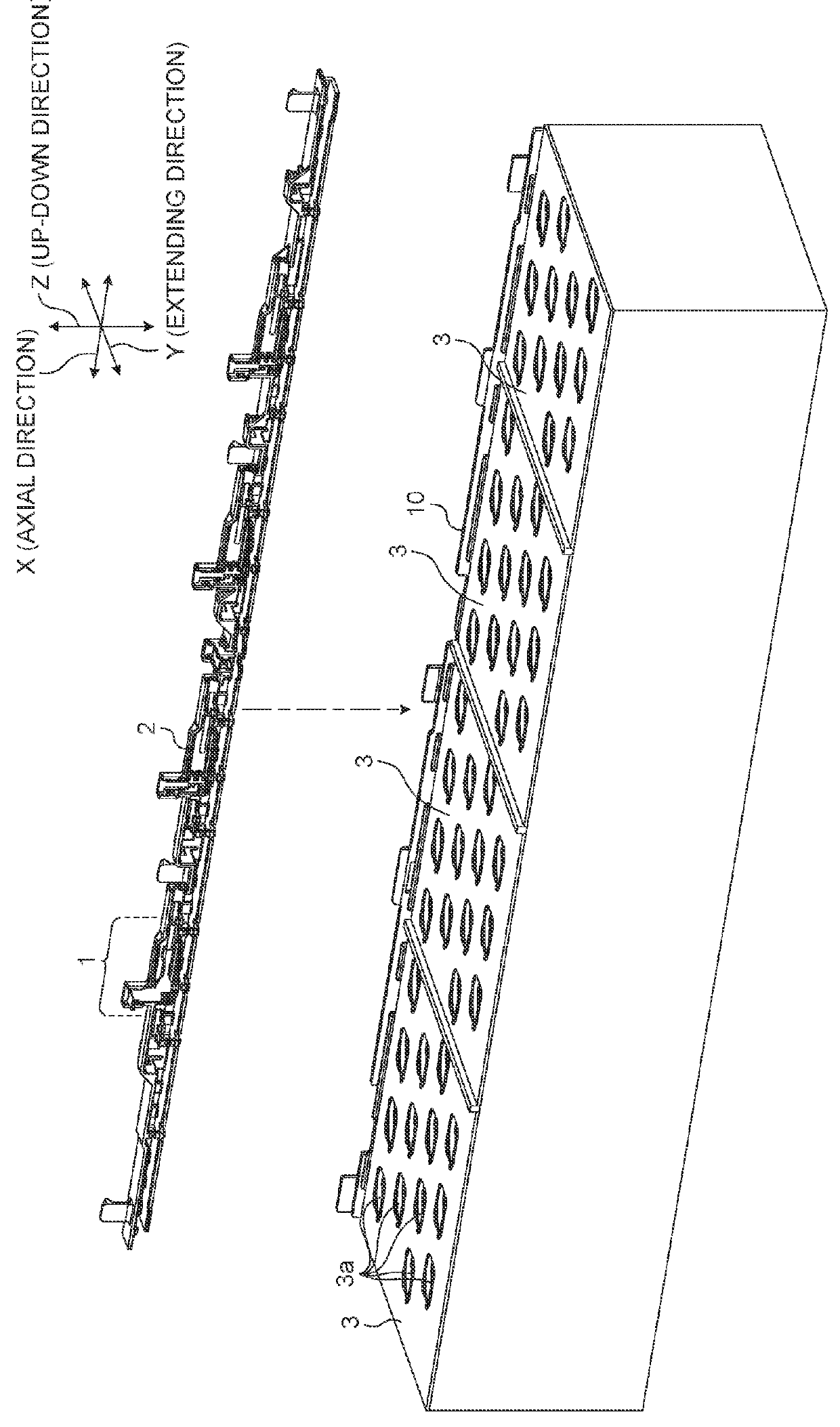
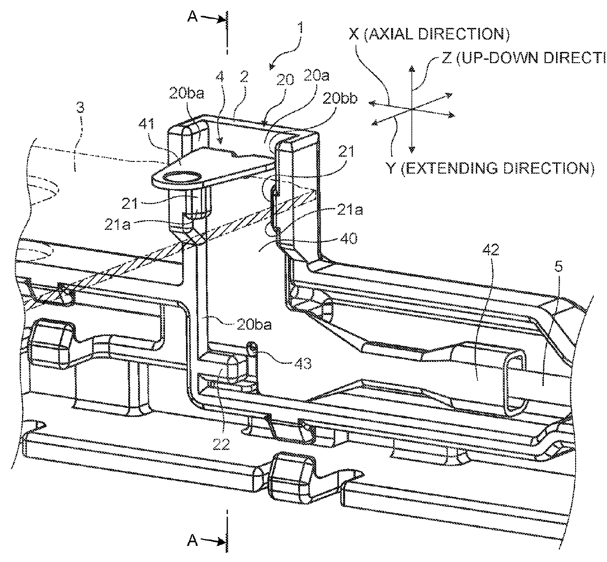
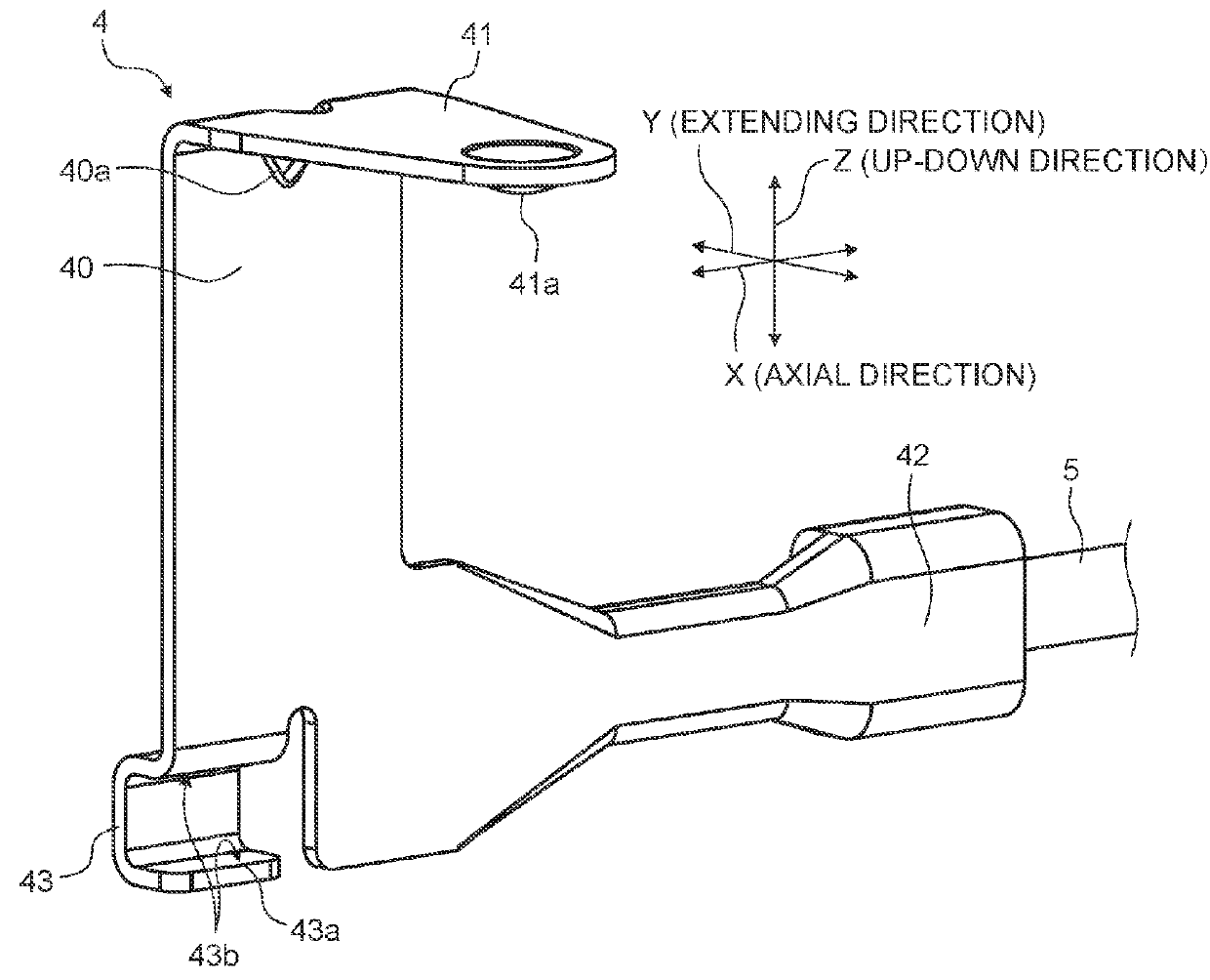
[0019]With reference to FIGS. 1 to 8, the following describes a fixing structure of voltage detection terminal according to the embodiment. FIG. 1 is an exploded perspective view illustrating a schematic structure of a battery pack to which the fixing structure of voltage detection terminal according to the embodiment is applied. FIG. 2 is a perspective view illustrating a schematic structure of the fixing structure of voltage detection terminal according to the embodiment. FIG. 3 is a perspective view illustrating a schematic structure of a voltage detection terminal in the embodiment. FIG. 4 is a partially enlarged view illustrating a schematic structure of a latch projection in embodiment. FIG. 5 is a longitudinal sectional view illustrating a schematic structure of the fixing structure of voltage detection terminal according to the embodiment. FIGS. 6 to 8 are schematic diagrams illustrating stages of a method for fixing the voltage detection terminal in the embodiment. FIG. 5 i...


PUM

PropertyMeasurementUnit
stressaaaaaaaaaa
electrical connectionaaaaaaaaaa
shapeaaaaaaaaaa

Abstract

A fixing structure of voltage detection terminal includes a voltage detection terminal and a resin case having insulation property. The voltage detection terminal includes a flat plate portion, a busbar connection portion that bends from an upper end of the flat plate portion in an extending direction perpendicular to an up-down direction, and a crimping portion connected to an end portion of an electrical wire. The resin case includes a terminal accommodating portion accommodating the voltage detection terminal. The busbar connection portion is bonded to a plane surface of a busbar in the up-down direction to overlap with the busbar. The terminal accommodating portion includes projections that block movement in the extending direction of the flat plate portion in the terminal accommodating portion, and a latch projection that blocks movement in the up-down direction of the voltage detection terminal in the terminal accommodating portion.

Description

CROSS-REFERENCE TO RELATED APPLICATION(S)[0001]The present application claims priority to and incorporates by reference the entire contents of Japanese Patent Application No. 2016-203626 filed in Japan on Oct. 17, 2016.BACKGROUND OF THE INVENTION1. Field of the Invention[0002]The present invention relates to a fixing structure of voltage detection terminal.2. Description of the Related Art[0003]Battery packs include housings and metal busbars that are fixed to electrode terminals of a plurality of battery cells housed in the housings and connect the battery cells in series and / or in parallel. In an example of such busbars, a part of a voltage detection terminal held by a resin case is bonded to a flat surface of the busbar by welding or soldering, for example (e.g., refer to Japanese Patent Application Laid-open No. 2015-187910).[0004]When rattling occurs between the resin case and the voltage detection terminal held by the resin case, a stress occurs in a portion where the voltage ...

Claims


Application Information

Patent Timeline
Patent Type & Authority Applications(United States)
IPC IPC(8): H01M10/48B60L11/18B60L3/00H01M2/20H01M2/30H01R11/28H01M50/204H01M50/296H01M50/50H01M50/503H01M50/522H01M50/569
CPCH01M10/48B60L11/1855B60L11/1879B60L3/0046H01M2/1077H01M2/305H01R11/288B60L2240/547H01M2/206H01M10/4207H01M50/50H01M50/503H01M50/296H01M50/569H01M50/522H01M50/204H01R9/16H01R11/12B60L50/64Y02T10/70Y02E60/10
Inventor TOMOBE, TAKUYAINOUE, NAOTO
Owner YAZAKI CORP
Why Eureka
Eureka Blog
Learn More