
Corn conveying machine

A conveyor, corn technology, applied in the direction of lifting device, hoisting device, etc.

Inactive Publication Date: 2007-08-08
邵传兵
View PDF0 Cites 0 Cited by
  • Summary
  • Abstract
  • Description
  • Claims
  • Application Information

AI Technical Summary

Problems solved by technology

[0003] The purpose of the present invention is to solve the problem that it is not easy to transport the corn to the roof for drying after harvesting in autumn, and to improve a corn conveyor with the advantages of simple structure, convenient use, saving manpower, and effectively improving labor efficiency.

Method used


Image

  • Corn conveying machine

Examples


Embodiment Construction

[0011] The present invention will be further described below in conjunction with the accompanying drawings and embodiments.

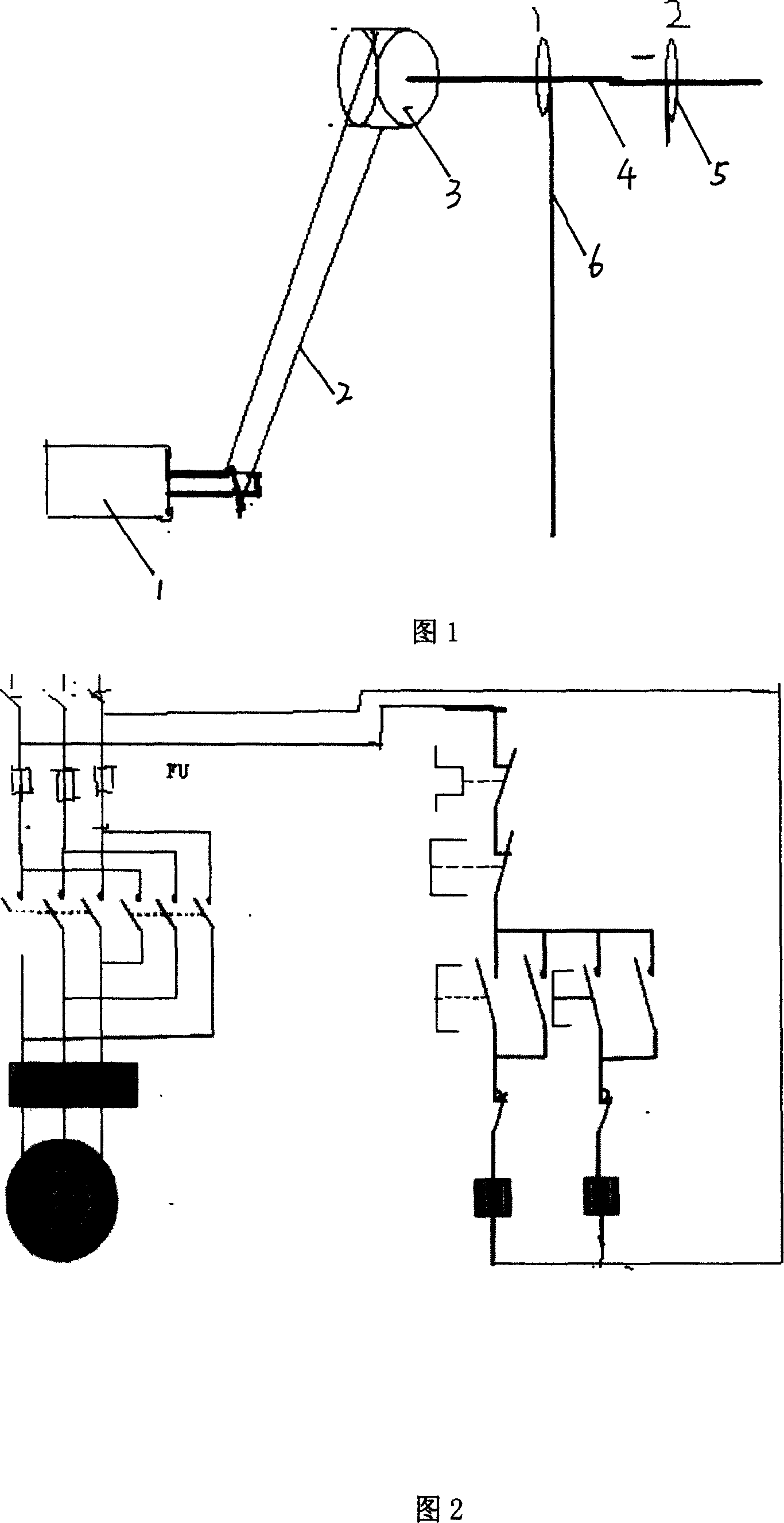
[0012] Among Fig. 1, motor 1 is installed on the frame, and it is connected with pulley 3 by V-belt 2, and the shaft of pulley 3 is connected with a crossbar 4, and crossbar 4 is provided with a pair of hoops 5 with pull cord, wherein The stay cord 6 of one iron ring 5 stretches out to the ground, the other stay cord 6 only exposes the iron ring 5, and the motor 1 is then connected with the control circuit.

[0013] In Figure 2, the control circuit is composed of a pair of start buttons, a contactor, a coil, a power supply, a thermal relay, and a knife switch to control the forward and reverse rotation of the motor; wherein, the motor passes the thermal relay, the thermal relay normally open contact Click on the power supply; the two start buttons are respectively connected in series with the coil and then in parallel, and connected to the power supply ...


PUM


Abstract

The invention relates to a corn transmitter, which is simple in structure, convenient in use, saving labor and improved in labor efficiency, which comprises generator installed on the chassis, the said generator connected to the triangle belt with the pulley, shaft of the pulley connecting with a horizontal bar, a pair of iron ring with pulling ropes on the horizontal bar, pulling rope of an iron ring sticking out of the land, the other pulling rope sticking out of the iron ring and the generator connected with the control circuit.

Description

technical field [0001] The invention relates to a corn conveyor, which belongs to the technical field of daily life. Background technique [0002] At present, when corn is harvested in autumn in the vast rural areas of China, the corn is usually transported to the roof for drying. The transportation method is mostly manual, that is, one person pulls the corn from the bottom of the house to the roof through a shoulder pole, one person on the roof sprinkles the corn on the roof, and one person below picks up the corn in the basket. In this way, it is very dangerous for people who use poles to pull corn (because they have been tired all day), and it is a waste of manpower. While the corn is being carried to the roof, there is no one to cook, feed the cattle, etc. At the same time, for families without male labor, it also makes it difficult to dry corn. Contents of the invention [0003] The purpose of the present invention is to solve the problem that it is difficult to tr...

Claims


Application Information

Patent Timeline
IPC IPC(8): B66F19/00
Inventor 邵传兵许福运
Owner 邵传兵
Learn More