A Pendulum Block Matching Cam Rotor Internal Combustion Engine Power System

A technology for internal combustion engines and cam rotors, applied to internal combustion piston engines, combustion engines, machines/engines, etc., can solve the problems of limited expandability of triangular rotor internal combustion engines, difficulty in improving rotor shaft torque, and difficulty in improving combustion utilization, etc. , to achieve the effect of short motion transmission link, simple structure and low manufacturing cost

Active Publication Date: 2020-05-19
DALIAN UNIV OF TECH
View PDF5 Cites 0 Cited by
  • Summary
  • Abstract
  • Description
  • Claims
  • Application Information

AI Technical Summary

Problems solved by technology

However, there are still key problems such as high processing requirements for core parts, too sensitive to wear, difficult adjustment of compression ratio, low thermal efficiency, etc., and it is still difficult to improve the combustion utilization rate
At the same time, similar to the piston internal combustion engine, the scalability of the triangular rotor internal combustion engine structure is also limited
In addition, when the expansion force generated by the fuel is converted into the power of the output shaft, there are natural defects in the transmission of force
Although the expansion force can push the rotor to rotate, it is difficult to increase the torque of the resultant force on the rotor shaft, and the proportion of internal friction is also too high

Method used


Image

  • A Pendulum Block Matching Cam Rotor Internal Combustion Engine Power System
  • A Pendulum Block Matching Cam Rotor Internal Combustion Engine Power System
  • A Pendulum Block Matching Cam Rotor Internal Combustion Engine Power System

Examples


Embodiment 1

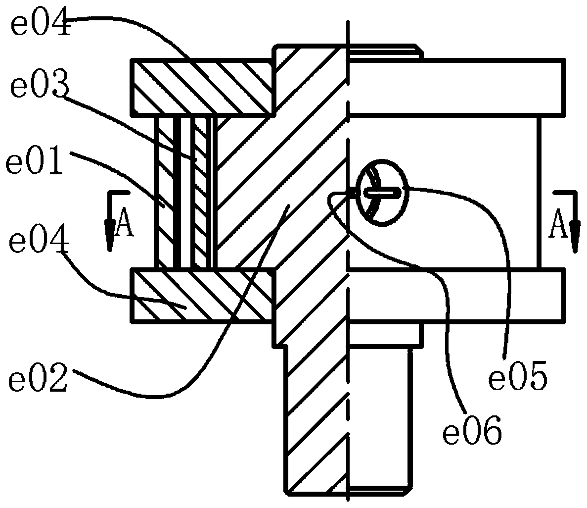
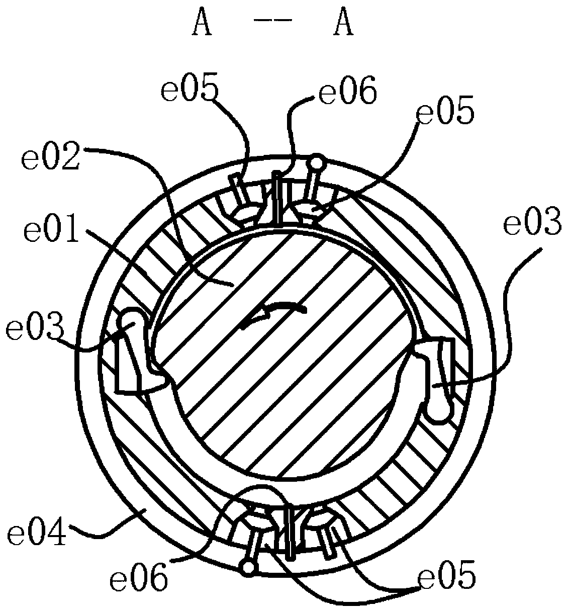
[0045] See attached image 3 , assuming that the rotor housing is fixed, the cam rotor is a disc cam with a far rest zone and a near rest zone, and the far and near rest angles are slightly less than 180°. The quantity of pendulum block is 2, symmetrically arranged. After assembly, the overall sealing relationship is as before, and will not be repeated. There is a small cylindrical surface in the center of the pendulum block, and a part of the concentric sealing cylindrical surface is also provided at the free end. In this way, the outside of the pendulum block can be fed with hydraulic oil to realize the force sealing of the contact between the cam and the pendulum block. There are two air inlets and two air outlets respectively, which are located on the rotor chamber and are located on both sides of the pendulum block, both of which are indicated by movable blocks representing the valves, and the corresponding air inlets with small circles. A pair of intake and exhaust por...

Embodiment 2

[0057] and then pass Figure 4 with 5 Demonstrate a slightly more complex situation.

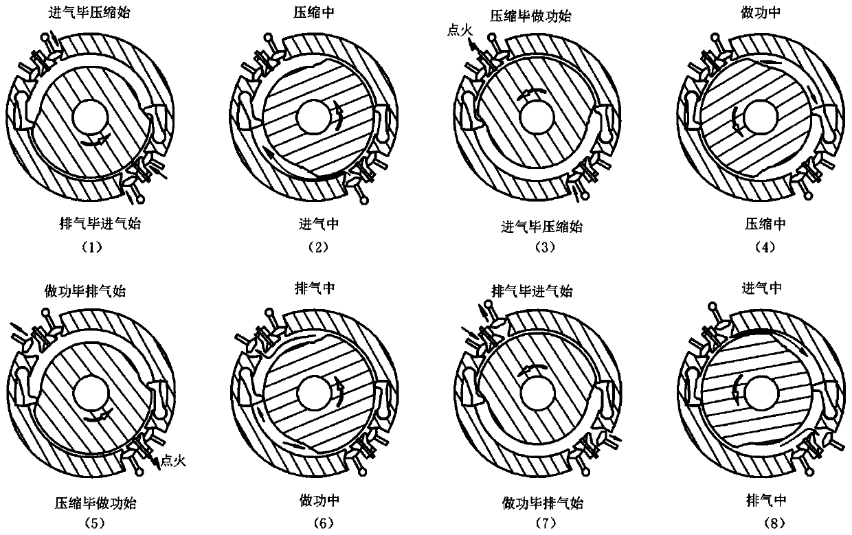
[0058] The rotor housing is fixed, and the cam rotor with cam profile is used as the output member. There are three pendulum blocks on the rotor housing to divide the rotor housing evenly into three sections. The cam rotor has a far rest area and a near rest area respectively. The corresponding central angles are similar, and the space between the two pendulum blocks is the working chamber or combustion chamber. Figure 4 with 5 It shows the corresponding valve state and working process in the chamber at different positions of the rotor. There are three working chambers, initially each chamber has two possible working processes, so there are 8 different combined working modes. Only two are shown here, and the rest will not be discussed one by one.

[0059] First mode:

[0060] Figure 4 It is the combination state of these three processes starting from the working chamber to start ai...

Embodiment 3

[0069] Image 6 Show variability further. As long as the circumferential space is large enough, the number of swing blocks and the number of cam protrusions (such as the far rest area) can be increased arbitrarily. With the addition of the pendulum block escapement, the size of the work space for completing each work cycle can also be changed.

[0070] The parameter relationships selected below are only for the convenience and clarity of description, and are not limiting. In the figure, it is assumed that the far resting segments of the cam rotor are evenly distributed, and the arc length of the resting segments is slightly larger than the corresponding arc lengths of the two adjacent pendulum blocks, so that the two pendulum blocks are retracted at the same time. The number of pendulum blocks is taken as 6 and evenly distributed, indicated by numbers. Each pendulum is controlled by the pendulum escapement, where "out of control" means that the pendulum has been released by...


PUM


Abstract

The invention relates to a swinging block and cam rotor cooperating internal combustion engine power system and belongs to the field of internal combustion engines. In the power system, cam rotors and a plurality of swinging driven parts are adopted to form a cam mechanism, the cam rotors, the swinging driven parts, rotor chambers and end members form a plurality of circumferentially distributed sealed working chambers; the volumes of the sealed working chambers are changed along with rotation of the cam rotors, and the four processes of air inflowing, compression, acting and exhausting of an otto cycle are finished in the working chambers through cooperation with air valves; and chemical energy generated by gas combustion is directly converted into fixed-shaft rotation type mechanical energy of the rotors. According to the swinging block and cam rotor cooperating internal combustion engine power system, planetary motion of Wankel rotors and an inner chamber in a specific shape are not needed, high-pressure gas directly pushes the rotors to perform fixed-shaft rotation and power is output, the structure is simple, and the parameter adjustable range is wide. Flexible control is easy to achieve under control of an added swinging block escapement device, and compared with piston internal combustion engine and Wankel rotor internal combustion engine power systems, the swinging block and cam rotor cooperating internal combustion engine power system has much more outstanding advantages.

Description

technical field [0001] The invention belongs to the field of internal combustion engines, and relates to a pendulum block matching cam rotor internal combustion engine power system. Background technique [0002] The piston internal combustion engine is the earliest internal combustion engine that came out. Its characteristic is that the piston makes a reciprocating linear motion in the cylinder, and the output of the crankshaft rotary motion is realized through the crank slider mechanism. Within two weeks of crankshaft rotation, the cylinder completes a complete intake, compression, work, and exhaust four working processes, that is, the Otto cycle. It is generally believed that the piston internal combustion engine has the advantages of high thermal efficiency, compact structure, strong maneuverability, and easy operation and maintenance. It is even believed that the power device of the piston internal combustion engine, especially the mechanical structure, has reached the ...

Claims


Application Information

Patent Timeline
Patent Type & Authority Patents(China)
IPC IPC(8): F02B53/00F02B53/06F02B53/02F02B55/02F02B55/08
CPCF02B53/00F02B53/02F02B53/06F02B55/02F02B55/08Y02T10/12
Inventor 孙守林卞永宁张光临洪鹏飞杨扬王琳
Owner DALIAN UNIV OF TECH
Why Eureka
Try Eureka